Commissioning Manual
01/2017
29
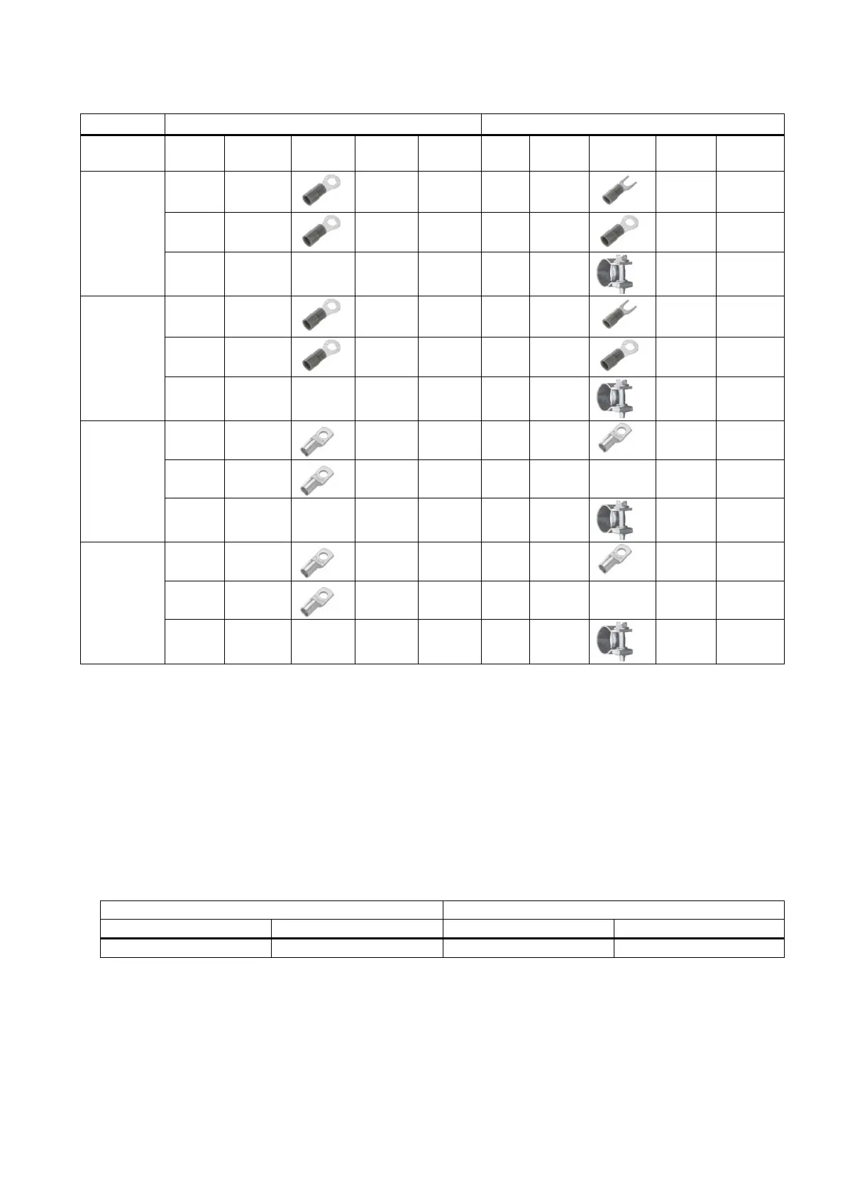
Recommended connectors for 1PH1 motor power cables
Cross-
Supplier Article
Picture Quantity
Used for Sup-
Article
Picture Quantity
Used for
4 × 2.5 mm
2
KST RNYL 2-5
3 U/V/W KST SNYL2-
4
3 U/V/W
KST RNYL 2-6
1 PE KST RNYL 2-
5
1 PE
- - - - - IDEAL 6204
1 Cable
shielding
4 × 4 mm
2
KST RNYL 5-5
3 U/V/W KST SNYL5-
5
3 U/V/W
KST RNY 5-6
1 PE KST RNY 5-5
1 PE
- - - - - IDEAL 6204
1 Cable
shielding
4 × 10 mm
2
KST TLK 10-5
3 U/V/W KST TLK 10-
5
4 U/V/W/PE
KST TLK 10-6
1 PE - - - - -
- - - - - IDEAL 62P08
1 Cable
shielding
4 × 16 mm
2
KST TLK 16-5
3 U/V/W KST TLK 16-
5
4 U/V/W/PE
KST TLK 16-6
1 PE - - - - -
- - - - - IDEAL 62P08
1 Cable
shielding
Options
External 24 VDC power supply
A 24 VDC power supply is used to supply the 808D ADVANCED and V70 servo drive. Consider the following technical
specification requirements when selecting a 24 VDC power supply:
● 24 VDC supplying the SINUMERIK 808D ADVANCED:
– Rated input voltage: 24 V
– Max. input voltage: 28.8 V
– Min. input voltage without output derating: 20.4 V
– Rated input current: 2.25 A
● 24 VDC supplying the SINAMICS V70 drive:
1)
1)
The minimum voltage of 24 VDC -10% must be available at the connector on the motor side in order to guarantee
that the brake reliably opens. If the maximum voltage of 24 VDC +10% is exceeded, then the brake could re-close.
The voltage drop along the brake feeder cable must be taken into consideration. The voltage drop ΔU for copper ca-
bles can be approximately calculated as follows:
ΔU [V] = 0.042 ∙ (l/q) ∙ I
Brake
Where: l = Cable length [m], q = Brake core cross section [mm
2
], I
Brake
= DC current of brake [A]

 Loading...


