Creating a G code program
7.4 Fundamentals
Turning
Operating Manual, 01/2015, 6FC5398-8CP40-5BA2
219
Blank input (Page 222)
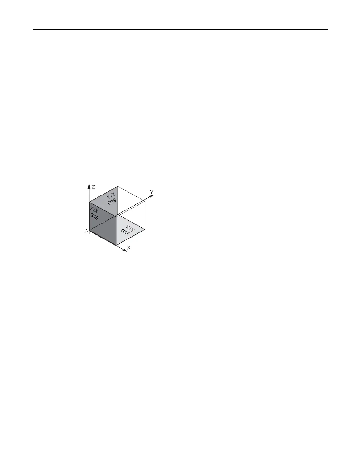
A plane is defined by means of two coordinate axes. The third coordinate axis (tool axis) is
perpendicular to this plane and determines the infeed direction of the tool (e.g. for 2½-D
machining).
When programming, it is necessary to specify the working plane so that the control system
can calculate the tool offset values correctly. The plane is also relevant to certain types of
circular programming and polar coordinates.
Working planes are defined as follows:
Current planes in cycles and input screens
Each input screen has a selection box for the planes, if the planes have not been specified
by NC machine data.
● Empty (for compatibility reasons to screen forms without plane)
● G17 (XY)
● G18 (ZX)
● G19 (YZ)

 Loading...


