Programming technology functions (cycles)
9.2 Rotate
Turning
358 Operating Manual, 01/2015, 6FC5398-8CP40-5BA2
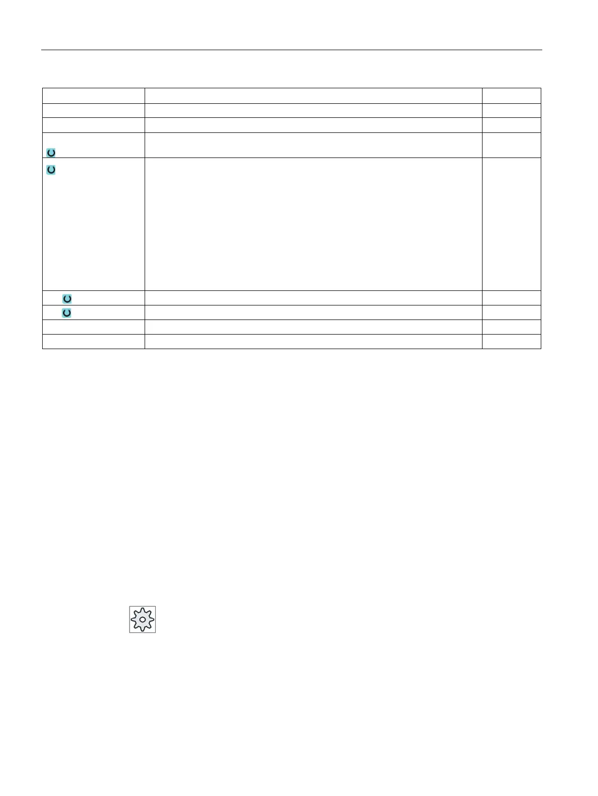
Finishing allowance in X – (not for finishing)
UZ Finishing allowance in Z – (not for finishing) mm
FS1...FS3 or R1...R3
Chamfer width (FS1...FS3) or rounding radius (R1...R3) - (not for
mm
Parameter selection of intermediate point
The intermediate point can be determined through position specification or angle.
The following combinations are possible - (not for stock removal 1 and 2)
• XM ZM
• XM α1
• XM α2
• α1 ZM
• α2 ZM
• α1 α2
Intermediate point X ∅ (abs) or intermediate point X in relation to X0 (inc)
Intermediate point Z (abs or inc)
* Unit of feedrate as programmed before the cycle call
Groove (CYCLE930)
Function
You can use the "Groove" cycle to machine symmetrical and asymmetrical grooves on any
straight contour elements.
You have the option of machining outer or inner grooves, longitudinally or transversely
(face). Use the "Groove width" and "Groove depth" parameters to determine the shape of the
groove. If a groove is wider than the active tool, it is machined in several cuts. The tool is
moved by a maximum of 80% of the tool width for each groove.
You can specify a finishing allowance for the groove base and the flanks; roughing is then
performed down to this point.
The dwell time between recessing and retraction is stored in a setting data element.
Please also refer to the machine manufacturer's specifications.