Programming technology functions (cycles)
9.7 Additional cycles and functions in ShopTurn
Turning
Operating Manual, 01/2015, 6FC5398-8CP40-5BA2
597
If a workpiece has been dimensioned from a central point (pole) with radius and angles, you
will find it helpful to program these dimensions as polar coordinates.
Before you program a straight line or circle in polar coordinates, you must define the pole,
i.e. the reference point, of the polar coordinate system.
The ShopTurn program to be processed has been created and you are
in the editor.
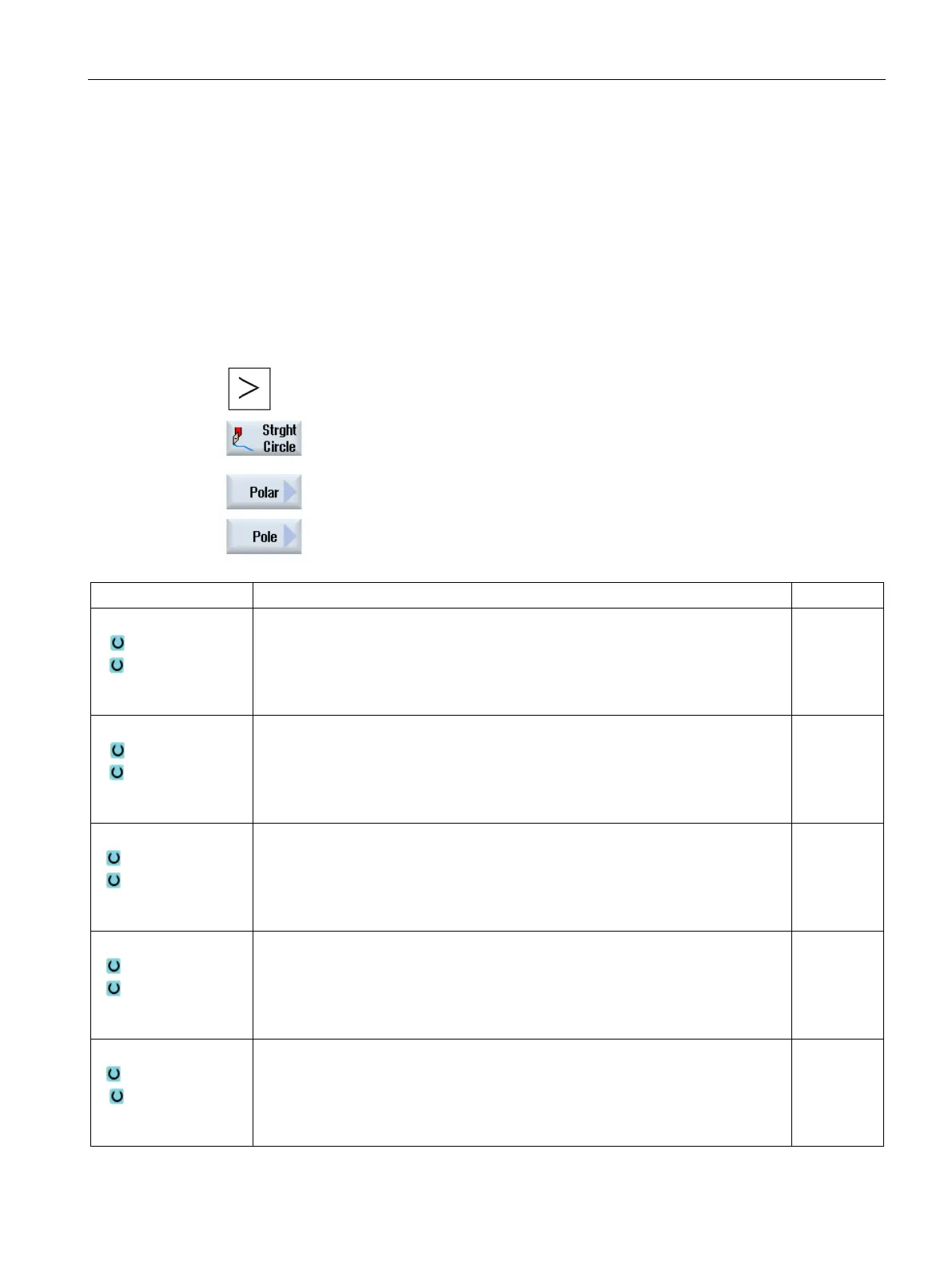
Press the menu forward key and the "Straight Circle" softkey.
Press the "Polar" and "Pole" softkeys.
Y
Z
Machining plane peripheral surface/peripheral surface C
Pole Y (abs)
Pole Z (abs) or pole Z referred to the last programmed position (inc)
Note:
Incremental dimension: The sign is also evaluated.
mm
mm
Y
Z
Machining plane, peripheral surface Y
Pole Y (abs)
Pole Z (abs) or pole Z referred to the last programmed position (inc)
Note:
Incremental dimension: The sign is also evaluated.
mm
mm
X
Y
Machining plane face/face C
Pole X ∅ (abs)
Pole Y (abs) or pole Y referred to the last programmed position (inc)
Note:
Incremental dimension: The sign is also evaluated.
mm
mm
X
Y
Pole X (abs)
Pole Y (abs) or pole Y referred to the last programmed position (inc)
Note:
Incremental dimension: The sign is also evaluated.
mm
mm
X
Z
Pole X (abs) or pole X referred to the last programmed position (inc)
Z position pole (abs)
Note:
Incremental dimension: The sign is also evaluated.
mm
mm

 Loading...


