Creating a ShopTurn program
8.4 Fundamentals
Turning
Operating Manual, 01/2015, 6FC5398-8CP40-5BA2
245
Absolute and incremental dimensions
When generating a machining step program, you can input positions in absolute or
incremental dimensions, depending on how the workpiece drawing is dimensioned.
You can also use a combination of absolute and incremental dimensions, i.e. one coordinate
as an absolute dimension and the other as an incremental dimension.
For the face axis (the X axis, in this case), in the machine data it is established whether the
diameter or radius is programmed in absolute or incremental dimensions.
Please refer to the machine manufacturer's specifications.
Absolute dimensions (ABS)
With absolute dimensions, all position specifications refer to the zero point of the active
coordinate system.
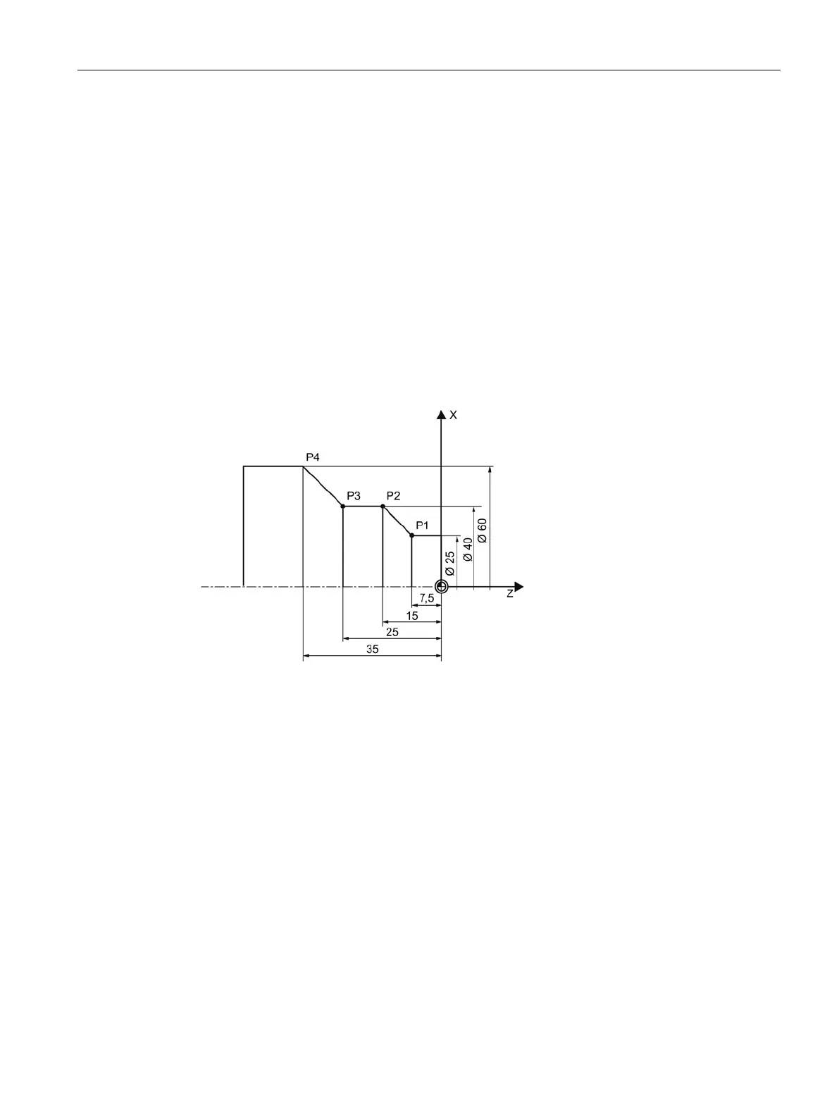
Figure 8-7 Absolute dimensions
The position specifications for the points P1 to P4 in absolute dimensions refer to the zero
point:
P1: X25 Z-7.5
P2: X40 Z-15
P3: X40 Z-25
P4: X60 Z-35