Working with a B axis (only 840D sl)
16.8 Measuring a tool with the B axis
Turning
Operating Manual, 01/2015, 6FC5398-8CP40-5BA2
833
Measuring a tool with the B axis
When measuring manually, traverse the tool manually to a known reference point in order to
determine the tool dimensions in the X and Z directions. The control system then calculates
the tool offset data from the position of the tool carrier reference point and the reference
point.
To determine the tool dimensions, the orientation, i.e. the β angle, must be specified.
The γ angle input box is also provided for turning tools.
The workpiece edge is used as the reference point when measuring length X and length Z.
The chuck of the main or counterspindle can also be used when measuring in the Z
direction.
Specify the position of the workpiece edge during the measurement.
In order to measure milling and turning tools, you can select the two main settings β = 0° and
β = 90° and a value input field.
In order to measure turning tools, you can select the γ angle 0° and 180°.
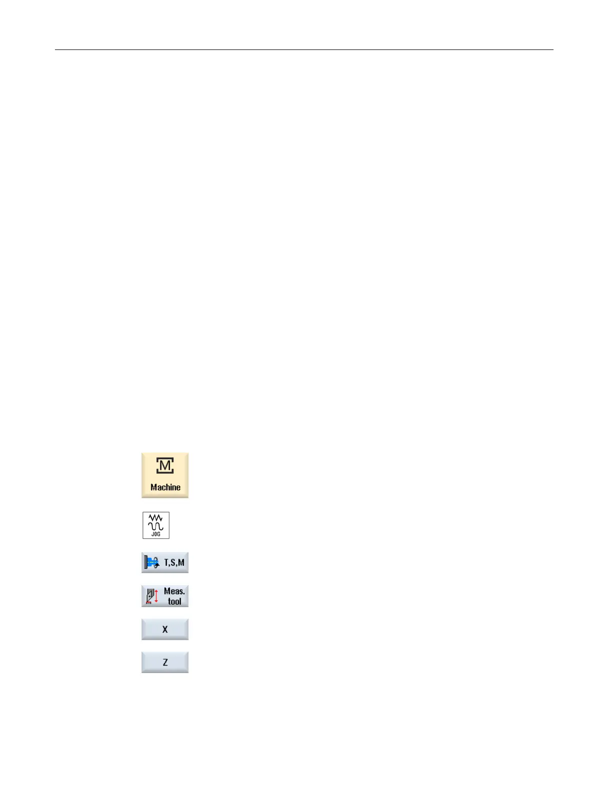
Select "JOG" mode in the "Machine" operating area.
Execute the tool change and alignment in the T, S, M window b
efore
performing the measurement.
Press the "Meas. tool" softkey.
Press the "X" or "Z" softkey, depending on which tool length you want
to measure.
Scratch the required edge using the tool.

 Loading...


