PERIODIC MAINTENANCE
3-9
Example:
Valve pad number = 158
Rounded value = 160
New valve pad number = 160
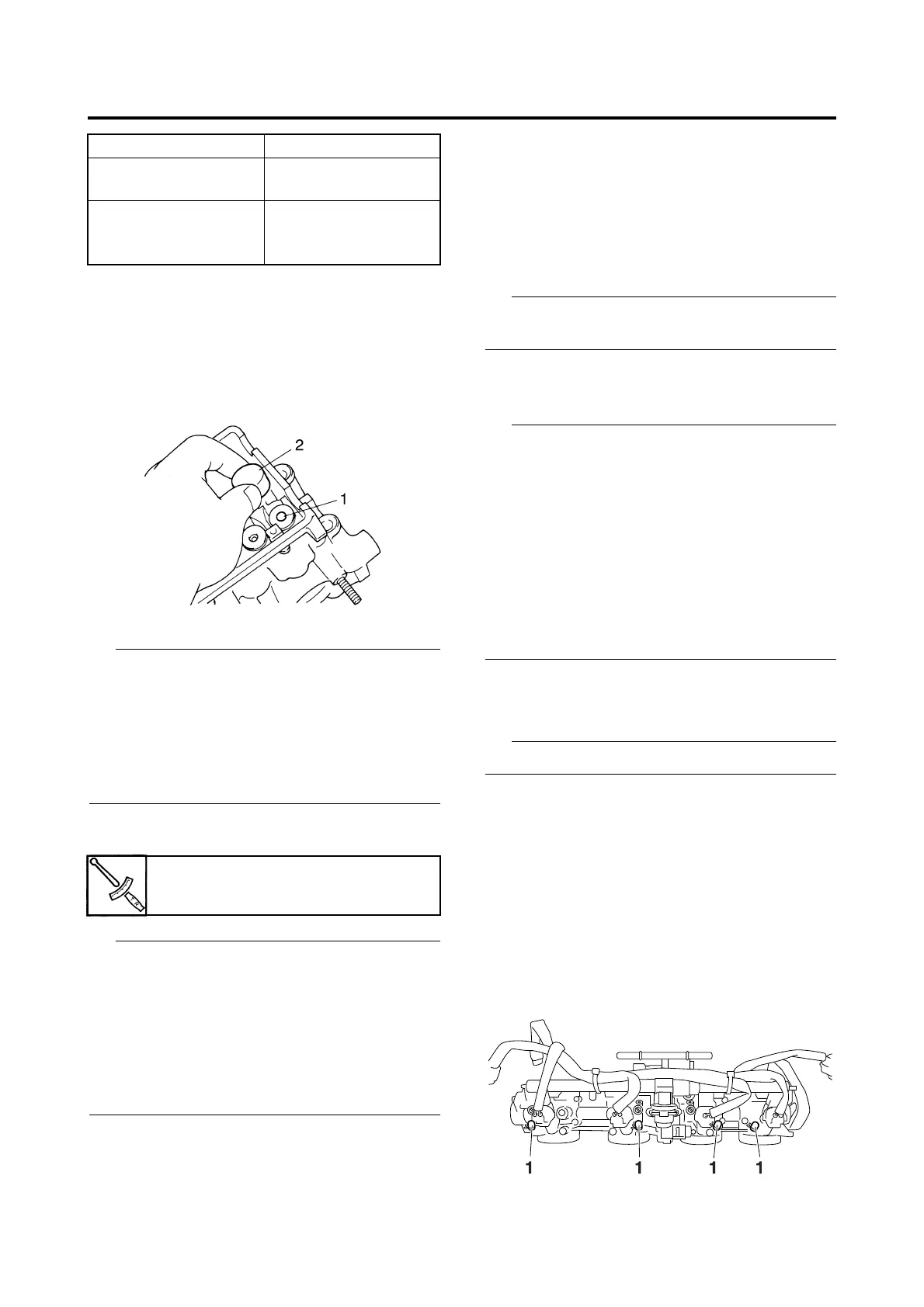
f. Install the new valve pad “1” and the valve
lifter “2”.
• Lubricate the valve pad with molybdenum
disulfide oil.
• Lubricate the valve lifter with engine oil.
• The valve lifter must turn smoothly when
rotated by finger.
• Install the valve lifter and the valve pad in the
correct place.
g. Install the exhaust and intake camshafts,
timing chain and camshaft caps.
• Refer to “CAMSHAFTS” on page 5-13.
• Lubricate the camshaft lobes and camshaft
journals.
• First, install the exhaust camshaft.
• Align the camshaft sprocket marks with the
camshaft cylinder head surface.
• Turn the crankshaft counterclockwise several
full turns to seat the parts.
h. Measure the valve clearance again.
i. If the valve clearance is still out of specifi-
cation, repeat all of the valve clearance
adjustment steps until the specified clear-
ance is obtained.
▲▲▲▲▲▲▲▲▲▲▲▲▲▲▲▲▲▲▲▲▲▲▲▲▲▲▲▲▲▲
7. Install:
• All removed parts
For installation, reverse the removal proce-
dure.
EAS20571
SYNCHRONIZING THE THROTTLE BODIES
Before synchronizing the throttle bodies, check
the following items:
• Valve clearance
• Spark plugs
• Air filter element
• Throttle body joints
• Fuel hoses
• Air induction system
• Exhaust system
• Breather hoses
• Vacuum hose
Checking the throttle body synchronization
1. Stand the vehicle on a level surface.
Place the vehicle on a suitable stand.
2. Remove:
• Rider seat
Refer to “GENERAL CHASSIS” on page
4-1.
• Fuel tank
Refer to “FUEL TANK” on page 7-1.
• Air filter case
Refer to “AIR FILTER CASE” on page 7-
5.
3. Remove:
•Caps “1”
Valve pad range No. 160–240
Valve pad thickness
1.60–2.40 mm
(0.0630–0.0945 in)
Available valve pads
17 thicknesses in
0.05 mm (0.0022 in)
increments
Camshaft cap bolt
10 Nm (1.0 m·kgf, 7.2 ft·lbf)

 Loading...