OIL PUMP
5-56
ECA14B1018
After installing the oil/water pump assem-
bly drive chain and drive sprocket, make
sure the oil/water pump turns smoothly.
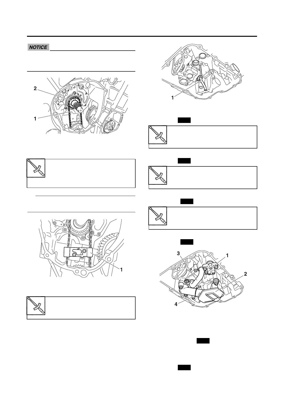
3. Install:
• Oil/water pump assembly drive chain
guide “1”
“UP” mark of the oil/water pump assembly
drive chain guide is upward.
4. Install:
• Oil delivery pipe 1 “1”
5. Install:
• Relief valve assembly “1”
• O-ring
• Oil strainer “2”
• O-ring
•Oil pipe “3”
• O-rings
• Drain pipe “4”
• O-rings
EAS25050
INSTALLING THE OIL PAN
1. Install:
• Dowel pins
• Oil pan gasket
• Oil pan
• Oil level switch lead holder
• Oil level switch
• O-ring
Oil/water pump assembly drive
chain guide bolt
10 Nm (1.0 m·kgf, 7.2 ft·lbf)
LOCTITE®
Oil delivery pipe 1 bolt
10 Nm (1.0 m·kgf, 7.2 ft·lbf)
LOCTITE®
Relief valve assembly bolt
10 Nm (1.0 m·kgf, 7.2 ft·lbf)
LOCTITE®
Oil strainer bolt
10 Nm (1.0 m·kgf, 7.2 ft·lbf)
LOCTITE®
Oil pipe bolt
10 Nm (1.0 m·kgf, 7.2 ft·lbf)
LOCTITE®

 Loading...