CRANKSHAFT
5-89
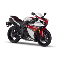
• Align the projections “a” of the balancer shaft
journal lower bearings with the notches “b” in
the lower crankcase.
• Do not move the balancer shaft until the
clearance measurement has been com-
pleted.
f. Tighten the bolts to specification in the
tightening sequence cast on the crankcase.
Refer to “CRANKCASE” on page 5-70.
g. Remove the lower crankcase and the bal-
ancer shaft journal lower bearings.
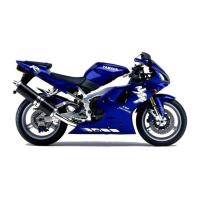
h. Measure the compressed Plastigauge®
width “a” on each balancer shaft journal.
If the balancer shaft-journal-to-balancer
shaft-journal-bearing clearance is out of
specification, select replacement balancer
shaft journal bearings.
▲▲▲▲▲▲▲▲▲▲▲▲▲▲▲▲▲▲▲▲▲▲▲▲▲▲▲▲▲▲
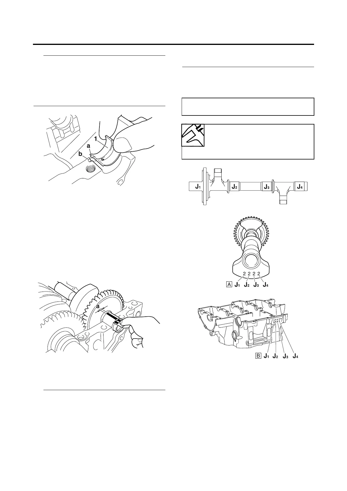
4. Select:
• Balancer shaft journal bearings (J
1
–J
4
)
• The numbers “A” stamped into the balancer
shaft web and the numbers “B” stamped into
the lower crankcase are used to determine
the replacement balancer shaft journal bear-
ing sizes.
•J
1
–J
4
refer to the bearings shown in the bal-
ancer shaft illustration.
• If J
1
–J
4
are the same, use the same size for
all of the bearings.
For example, if the crankcase J
1
and bal-
ancer shaft web J
1
numbers are 6 and 2
respectively, then the bearing size for J
1
is:
EAS26200
INSTALLING THE CRANKSHAFT
1. Install:
• Crankshaft journal upper bearings
(into the upper crankcase)
• Crankshaft journal lower bearings
(into the lower crankcase)
• Crankshaft
J
1
(crankcase) - J
1
(balancer shaft web) - 1 =
6 - 2 - 1 = 3 (brown)
Bearing color code
0.White 1.Blue 2.Black
3.Brown 4.Green 5.Yellow
6.Pink

 Loading...