CONNECTING RODS AND PISTONS
5-76
2. Measure:
• Piston-to-cylinder clearance
▼▼▼▼▼▼▼▼▼▼▼▼▼▼▼▼▼▼▼▼▼▼▼▼▼▼▼▼▼▼
a. Measure cylinder bore “C” with the cylinder
bore gauge.
Measure cylinder bore “C” by taking side-to-
side and front-to-back measurements of the
cylinder. Then, find the average of the mea-
surements.
b. If out of specification, replace the cylinder,
and replace the piston and piston rings as
a set.
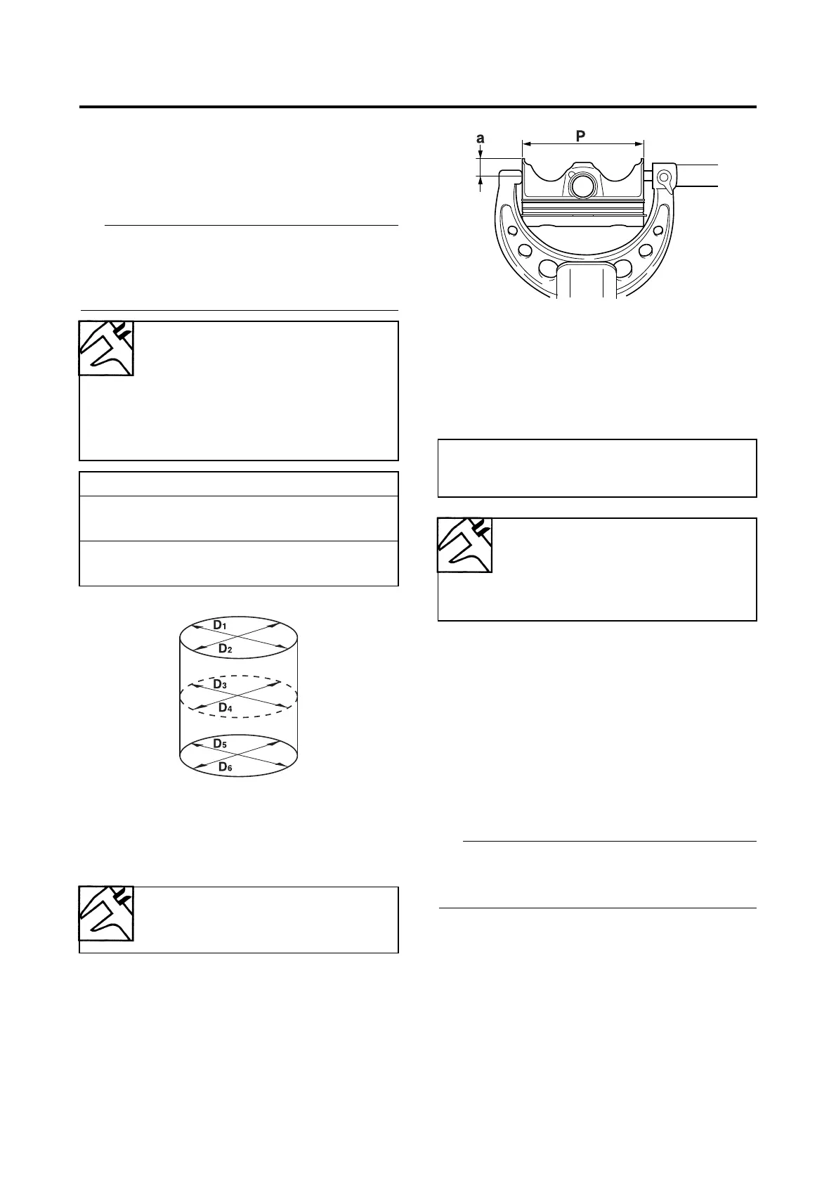
c. Measure piston skirt diameter “P” with the
micrometer.
d. If out of specification, replace the piston
and piston rings as a set.
e. Calculate the piston-to-cylinder clearance
with the following formula.
f. If out of specification, replace the cylinder,
and replace the piston and piston rings as
a set.
▲▲▲▲▲▲▲▲▲▲▲▲▲▲▲▲▲▲▲▲▲▲▲▲▲▲▲▲▲▲
EAS24430
CHECKING THE PISTON RINGS
1. Measure:
• Piston ring side clearance
Out of specification → Replace the piston
and piston rings as a set.
Before measuring the piston ring side clear-
ance, eliminate any carbon deposits from the
piston ring grooves and piston rings.
Bore
78.000–78.010 mm (3.0709–
3.0713 in)
Taper limit
0.050 mm (0.0020 in)
Out of round limit
0.050 mm (0.0020 in)
“C” = maximum of D
1
–D
6
Taper limit = maximum of D
1
or D
2
- maxi-
mum of D
5
or D
6
Out of round limit = maximum of D
1
, D
3
or D
5
- minimum of D
2
, D
4
or D
6
Piston diameter
77.975–77.990 mm (3.0699–
3.0705 in)
a. 12 mm (0.47 in) from the bottom edge of
the piston
Piston-to-cylinder clearance =
Cylinder bore “C” -
Piston skirt diameter “P”
Piston-to-cylinder clearance
0.010–0.035 mm (0.0004–
0.0014 in)
Limit
0.150 mm (0.0059 in)

 Loading...