VALVES AND VALVE SPRINGS
5-34
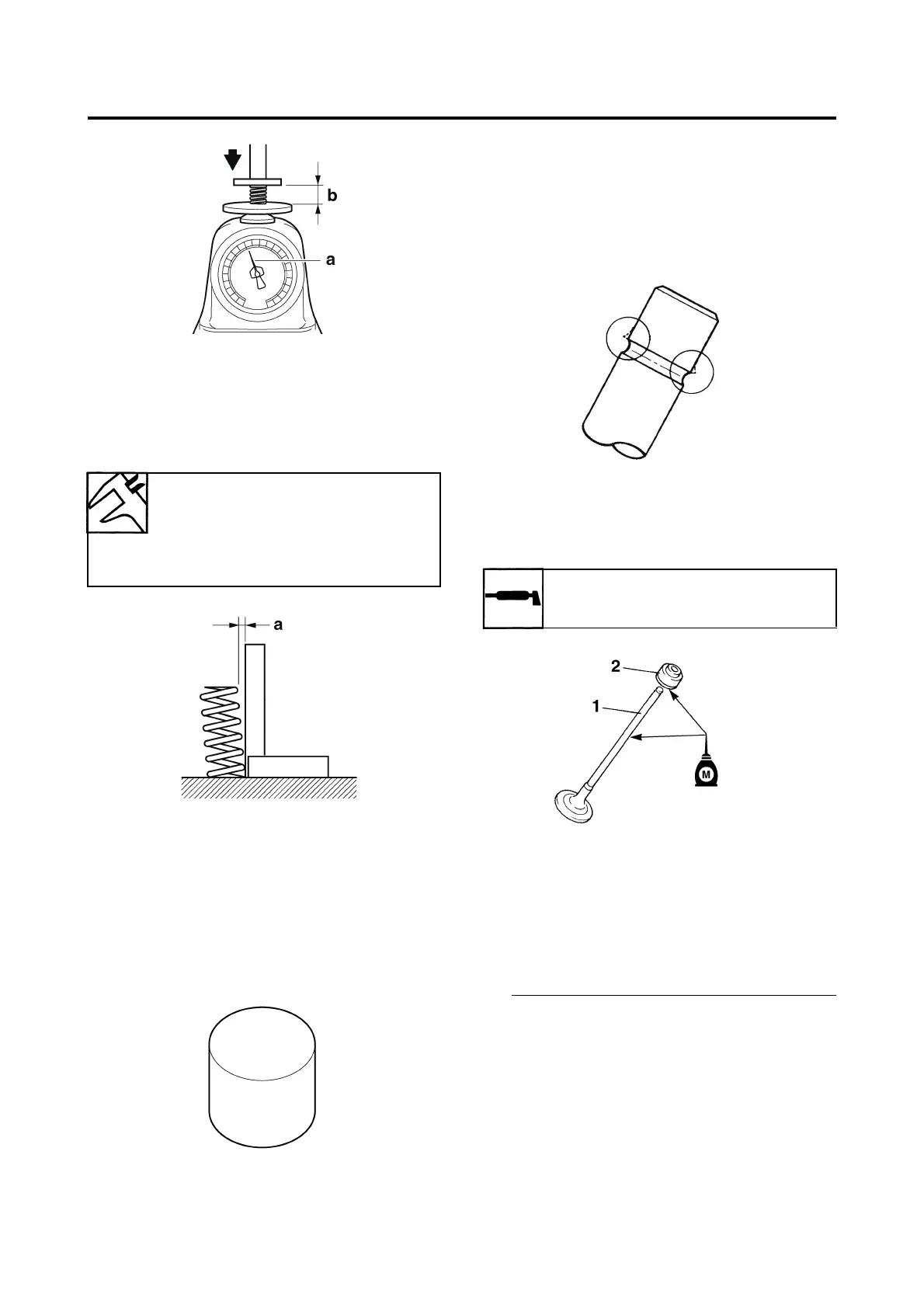
3. Measure:
• Valve spring tilt “a”
Out of specification → Replace the valve
spring.
EAS24320
CHECKING THE VALVE LIFTERS
The following procedure applies to all of the
valve lifters.
1. Check:
• Valve lifter
Damage/scratches → Replace the valve
lifters and cylinder head.
EAS24340
INSTALLING THE VALVES
The following procedure applies to all of the
valves and related components.
1. Deburr:
• Valve stem end
(with an oil stone)
2. Lubricate:
• Valve stem “1”
• Valve stem seal “2”
(with the recommended lubricant)
3. Install:
• Valve spring seat “1”
• Valve stem seal “2”
•Valve “3”
•Valve spring “4”
• Valve spring retainer “5”
(into the cylinder head)
• Make sure each valve is installed in its origi-
nal place. Refer to the following embossed
marks.
Intake valve: Blue paint mark
Exhaust valve: “14B”
• Install the valve springs with the larger pitch
“a” facing up.
b. Installed length
Spring tilt limit
Spring tilt (intake)
2.5°/1.7 mm (0.067 in)
Spring tilt (exhaust)
2.5°/1.7 mm (0.067 in)
Recommended lubricant
Molybdenum disulfide oil

 Loading...