PERIODIC MAINTENANCE
3-12
7. Check:
• Tightening torque
8. Install:
• Radiator lower bracket
Refer to “RADIATOR” on page 6-1.
9. Install:
• Rear brake master cylinder
Refer to “REAR BRAKE” on page 4-44.
10. Install:
• Side cowlings
Refer to “GENERAL CHASSIS” on page
4-1.
11. Install:
• Passenger seat
Refer to “GENERAL CHASSIS” on page
4-1.
12. Install:
• Rider seat
Refer to “GENERAL CHASSIS” on page
4-1.
EAS20600
ADJUSTING THE EXHAUST GAS VOLUME
Be sure to set the CO density level to stan-
dard, and then adjust the exhaust gas volume.
1. Turn the main switch to “OFF” and set the
engine stop switch to “ON”.
2. Simultaneously press and hold the
“SELECT” and “RESET” buttons, turn the
main switch to “ON”, and continue to press
the buttons for 8 seconds or more.
“dIAG” appears on the odometer, tripmeter and
fuel reserve trip LCD.
3. Press the “SELECT” button to select the
CO adjustment mode “CO” or the diagnos-
tic mode “dIAG”.
4. After selecting “CO”, simultaneously press
the “SELECT” and “RESET” buttons for 2
seconds or more to execute the selection.
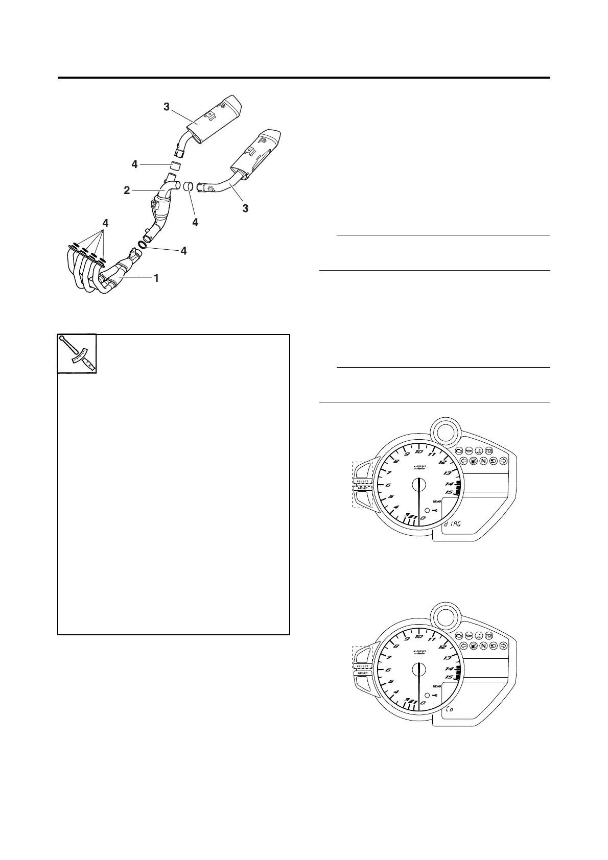
Exhaust pipe nut
20 Nm (2.0 m·kgf, 14 ft·lbf)
Exhaust pipe and exhaust
chamber clamp bolt
10 Nm (1.0 m·kgf, 7.2 ft·lbf)
Exhaust pipe and exhaust pipe
stay bolt
20 Nm (2.0 m·kgf, 14 ft·lbf)
Exhaust chamber bracket bolt
20 Nm (2.0 m·kgf, 14 ft·lbf)
Exhaust chamber bolt
20 Nm (2.0 m·kgf, 14 ft·lbf)
Exhaust chamber and left muf-
fler bolt
20 Nm (2.0 m·kgf, 14 ft·lbf)
Exhaust chamber and right muf-
fler bolt
20 Nm (2.0 m·kgf, 14 ft·lbf)
Left muffler and frame bolt
23 Nm (2.3 m·kgf, 17 ft·lbf)
Right muffler and frame bolt
23 Nm (2.3 m·kgf, 17 ft·lbf)
 Loading...