ELECTRICAL COMPONENTS
8-144
▼▼▼▼▼▼▼▼▼▼▼▼▼▼▼▼▼▼▼▼▼▼▼▼▼▼▼▼▼▼
a. Connect the pocket tester (Ω × 1 k) to the
accelerator position sensor terminal as
shown.
b. Measure the accelerator position sensor
maximum resistance.
▲▲▲▲▲▲▲▲▲▲▲▲▲▲▲▲▲▲▲▲▲▲▲▲▲▲▲▲▲▲
3. Install:
• Accelerator position sensor
When installing the accelerator position sen-
sor, adjust its angle properly. Refer to
“ADJUSTING THE ACCELERATOR POSI-
TION SENSOR” on page 7-19.
EAS14B1061
CHECKING THE THROTTLE SERVO
MOTOR
1. Remove:
• Air filter case
Refer to “AIR FILTER CASE” on page 7-
5.
2. Check:
• Throttle servo motor resistance
Out of specification → Replace the throt-
tle body assembly.
▼▼▼▼▼▼▼▼▼▼▼▼▼▼▼▼▼▼▼▼▼▼▼▼▼▼▼▼▼▼
a. Disconnect the throttle servo motor coupler
from wire harness.
b. Connect the digital circuit tester to the
throttle servo motor coupler.
c. Measure the throttle servo motor resis-
tance.
▲▲▲▲▲▲▲▲▲▲▲▲▲▲▲▲▲▲▲▲▲▲▲▲▲▲▲▲▲▲
EAS28370
CHECKING THE AIR INDUCTION SYSTEM
SOLENOID
1. Check:
• Air induction system solenoid resistance
Out of specification → Replace.
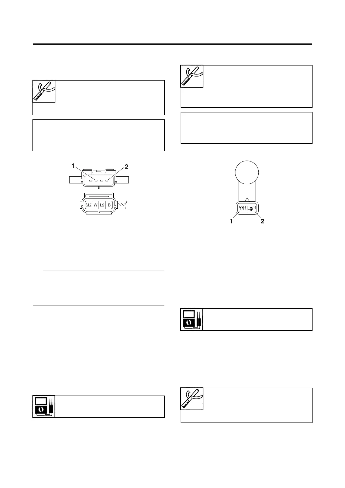
▼▼▼▼▼▼▼▼▼▼▼▼▼▼▼▼▼▼▼▼▼▼▼▼▼▼▼▼▼▼
a. Disconnect the air induction system sole-
noid coupler from the air induction system
solenoid.
b. Connect the pocket tester (Ω × 1) to the air
induction system solenoid terminal as
shown.
Pocket tester
90890-03112
Analog pocket tester
YU-03112-C
• Positive tester probe
Blue “1”
• Negative tester probe
Black/Blue “2”
Throttle servo motor resistance
1.23–1.67 Ω
Digital circuit tester
90890-03174
Model 88 Multimeter with
tachometer
YU-A1927
• Positive tester probe
Yellow/Red “1”
• Negative tester probe
Light green/Red “2”
Solenoid resistance
18–22 Ω at 20 °C (68 °F)
Pocket tester
90890-03112
Analog pocket tester
YU-03112-C

 Loading...