Page 4-58 110XiIIIPlus Maintenance Manual 13185L-002 Rev. A 1/24/06
Section 4 Maintenance
7. Remove the new cutter PCB from the antistatic bag and position it onto the
standoffs.
8. Refer to Figure 4-34. Connect the cutter power cable to connector J2.
9. Connect the cutter data cable to connector J1.
10. Route the cutter stepper motor wires between the two right-hand standoffs and
under the bottom of the PCB. Attach the motor wires to connector J4 on the new
cutter PCB. Ensure the black lead is to the left.
11. Refer to Figure 4-33. Secure the new cutter PCB to the standoffs with the screws
previously removed.
12. Refer to Figure 4-34. Connect the cutter optical sensor to the cutter optical
connector J3 on the new cutter PCB.
13. Dress all the wires to ensure no wiring touches any moving parts.
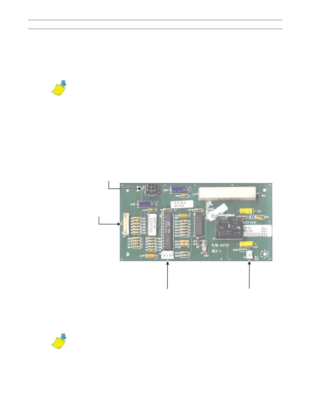
Figure 4-34. Cutter PCB Connections
14. Refer to RRP No. 3 on page 4-17 and reinstall the AC/DC power supply. Reconnect
all removed cables to the power supply.
15. Proceed to Align the Lower Drive Arm on page 4-59.
Note • The cutter motor leads have a polarized connector.
J4 to Stepper
Motor
J3 to Cutter
Optical Sensor
J1 to Main
Logic Board
J2 to DC
Power Supply
Note • When the cutter PCB is changed, the lower drive arm alignment must be
checked.
 Loading...