P1086708-001 ZXP Series 9 Card Printer Service Manual 347
Replacement Procedures for the Laminator
Removal Sequence
Removal Sequence
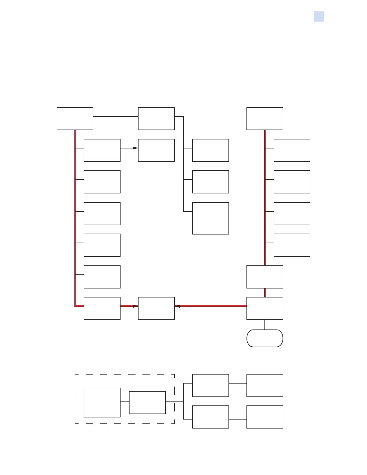
The following gures show the recommended removal sequence. For each item, follow the diagram
to see what must be removed for access.
To remove the Exit Rollers (page 395), rst remove the Back Cover (page 362), and the 24V
Heater Fans (page 363); then open the Laminator Door, and remove the Laminator Heater
Assembly (page 356) and the Front Frame (page 376)—follow the red path.
“Base-Frame Separation” on page 411
Back Cover
(Page 362)
Laminator
Lock
(Page 360)
Motor
and Plate
Assembly
(Page 365)
Bottom
Laminator
Control Motor
(Page 372)
Laminator
Controller
PCBA
(Page 368)
Staging Motor
(Page 373)
Media
Authentication
Antenna
PCBAs
(Page 374)
Open
Laminator
Media
Authentication
PCBA
(Page 370)
Top Laminator
Control Motor
(Page 371)
Card Entry
Sensor Cable
Assembly
(Page 401)
Door Sensor
Cable
Assembly
(Page 404)
Laminator
Beam
(Page 405)
24V Heater
Fans
(Page 363)
Exit Rollers
(Page 395)
Front Frame
(Page 376)
Laminator
Heater
Assembly
(Page 356)
Cruciform
Assembly
(Page 413)
Door Latch
(Page 414)
Frame
Base
Separate the
frame from the
base
Remove the
baseplate
from the frame
and base
assembly
Molded
Ribbon
Spindle
(Page 354)
Square
Corner
Spindle
(Page 355)
Halogen Bulbs
(Page 357)
Next Page
 Loading...