116 Rockwell Automation Publication 2094-UM002G-EN-P - August 2016
Chapter 5 Connect the Kinetix 6200 and Kinetix 6500 Drive System
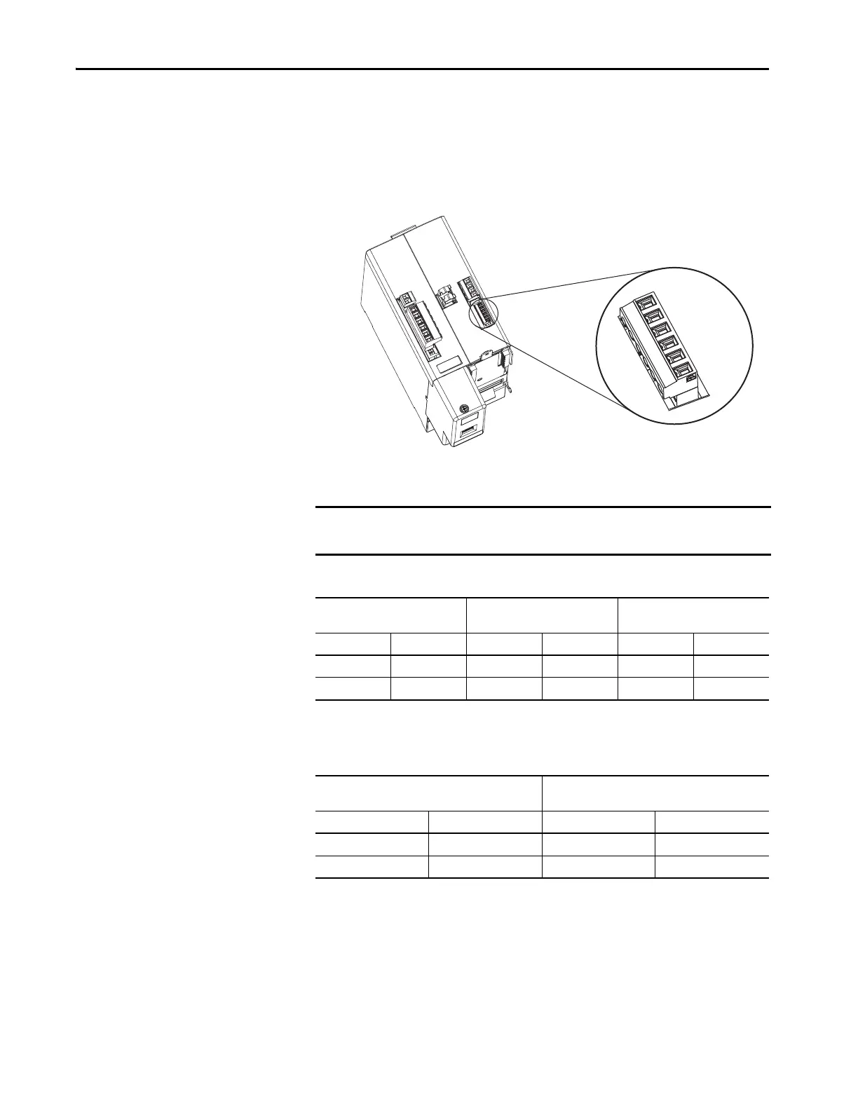
Wire the Motor/Resistive Brake (BC) Connector
This example applies to AM modules and the inverter section of IAM power
modules.
Figure 64 - IAM/AM Power Module (BC connector)
24V DC Brake Input Power Connections
Table 69 - Motor/Resistive Brake (BC) Connector
RBM Module Connections
Table 70 - Motor/Resistive Brake (BC) Connector
MBRK-
MBRK+
COM
PWR
DBRK-
DBRK+
1 2 3 4 5 6
Bulletin 2094
IAM/AM Power Module,
(IAM module is shown)
IMPORTANT If your system includes a LIM module, you can source the 24V DC from the
LIM module (P1L or PSL connector).
2094-BLxxS or 2094-XL75S-Cx
LIM Module
2094-BL02
LIM Module
BC Connector
(IAM/AM modules)
P1L Pin Signal PSL Pin Signal BC Pin Signal
1IO_PWR21MBRK PWR3PWR
2 IO_COM2 2 MBRK COM 4 COM
RBM Module I/O Connections
BC Connector
(IAM/AM power modules)
TB3 Pin Signal MP Pin Signal
(1)
(1) Firmware revision 1.071 or later is required to use the DBRK outputs on the Kinetix 6200 and Kinetix 6500 IAM/AM power
module.
6COIL_A11DBRK+
7COIL_A22DBRK-

 Loading...


