124 Rockwell Automation Publication 2094-UM002G-EN-P - August 2016
Chapter 5 Connect the Kinetix 6200 and Kinetix 6500 Drive System
Wiring the Feedback and I/O
Connectors
These procedures assume you have mounted your Kinetix 6200 and
Kinetix 6500 system, completed all power wiring, and are ready to connect
your feedback and I/O cables.
Connect Premolded Motor Feedback Cables
Motor feedback cables with premolded connectors plug directly into 15-pin
motor feedback (MF) connectors on the control modules (no wiring is
necessary).
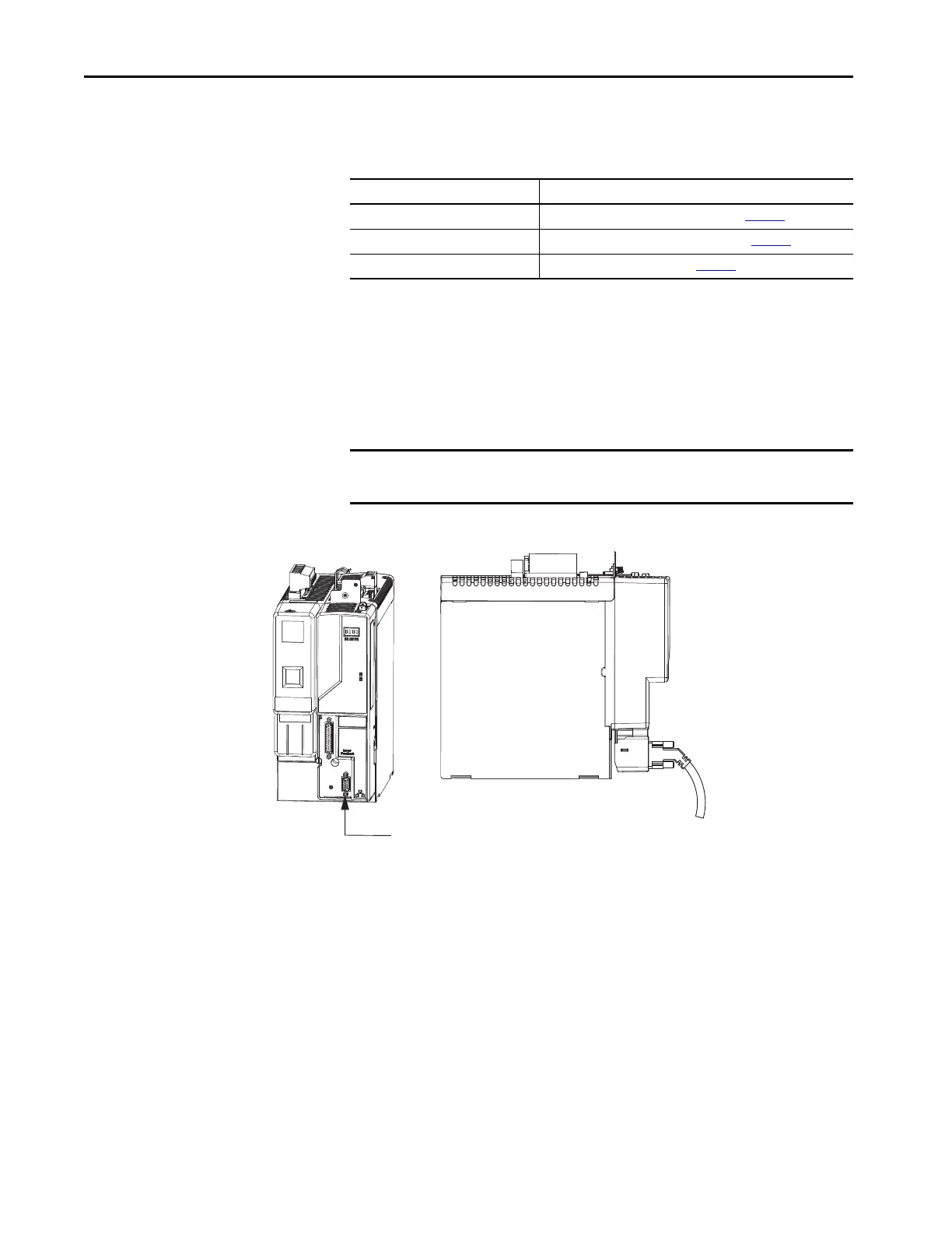
Figure 66 - IAM/AM Power Module/Control Module (MF connector)
For This Connection Go to
Premolded cable Connect Premolded Motor Feedback Cables on page 124
.
Panel-mounted breakout board Connect Panel-mounted Breakout Board Kits on page 125
.
Low-profile connector Wire Low-profile Connector Kits on page 126
.
IMPORTANT When using Bulletin 2090 cables with premolded connectors, tighten the
mounting screws (finger tight) to improve system performance.
Kinetix 6200 or Kinetix 6500, Front View
(IAM power module with
control module is shown)
Kinetix 6200 or Kinetix 6500, Side View
(IAM power module with
control module is shown)
Premolded Connector
(2090-UXNFBMP-Sxx Cable
Motor Feedback (MF) Connector

 Loading...


