Rockwell Automation Publication 2094-UM002G-EN-P - August 2016 131
Connect the Kinetix 6200 and Kinetix 6500 Drive System Chapter 5
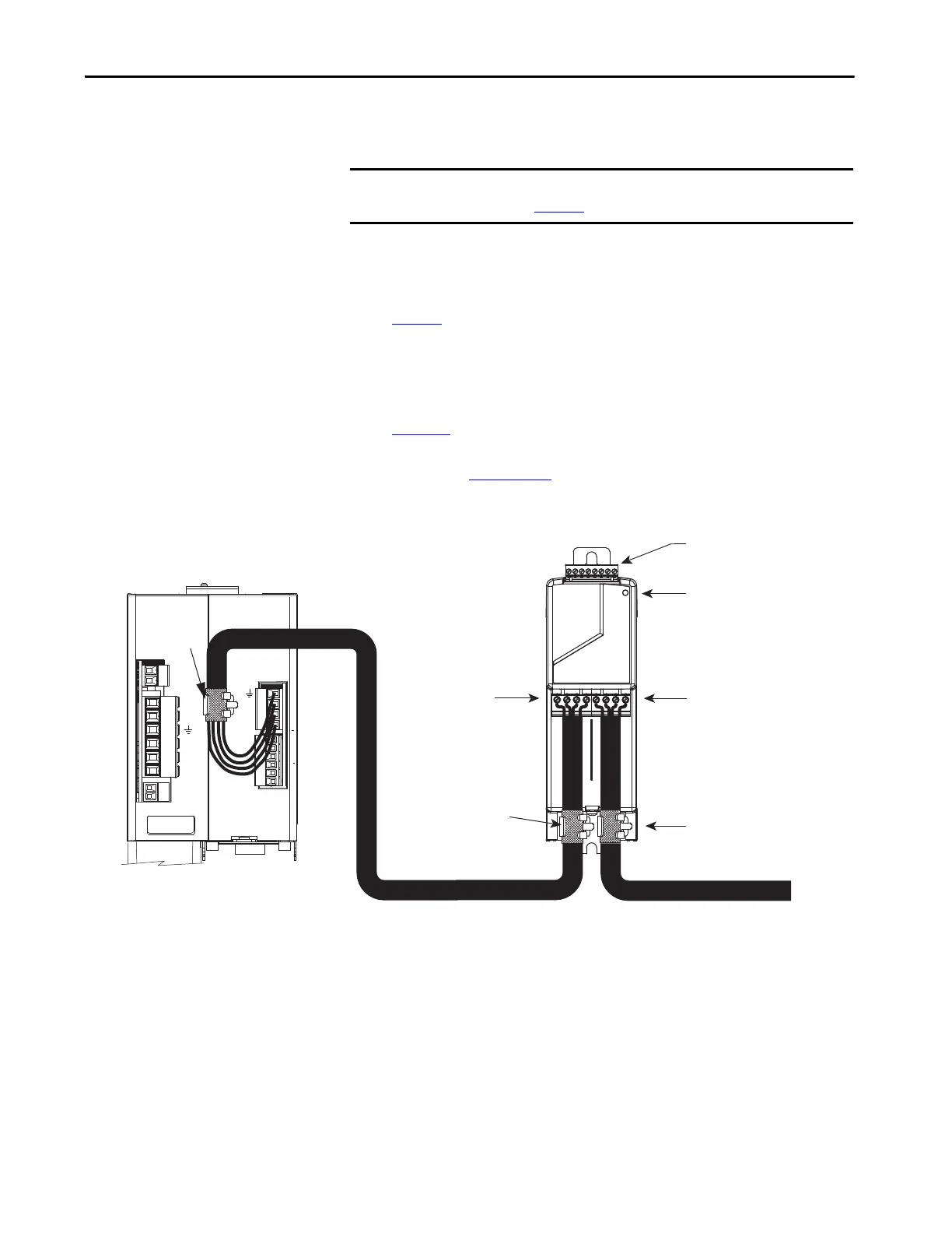
RBM Module Connections
Follow these guidelines when wiring your Bulletin 2090 Resistive Brake
Module (RBM).
If your application requires an RBM module and you are wiring to a Bulletin
2094 IAM/AM power module, then refer to the following:
• Cable Categories for Kinetix 6200 and Kinetix 6500 Systems on
page 47
to establish noise zones when mounting the RBM module on
your panel.
• Resistive brake module to Bulletin 2094 drive interface cable (catalog
number 2090-XXNRB-xxF0Px).
• The example diagram below and others in Appendix G, beginning on
page 313
.
• The installation instructions provided with your RBM module,
publication 2090-IN009
.
Figure 75 - RBM Module Connections
IMPORTANT To be sure of system performance, run wires and cables in the wireways as
established in Chapter
2.
1 2
DC-
DC+
L3
L2
L1
CONT EN-
CONT EN+
CTRL 2
CTRL 1
1 2
1 2 3 4 5 6
W
V
U
MBRK -
MBRK +
COM
PWR
DBRK -
DBRK +
1 2 3 4
1 2 3 4 5 6
I/O Connections
(TB3) Connector
Contactor Status Indicator
Motor Connections
(TB2) Connector
Drive Connection
(TB1) Connector
Motor Cable
Shield Clamps
RBM Module,
Front View
To Motor
Exposed Shield Braid
Under Clamp
2090-XXNRB-xxF0Px
RBM/Bulletin 2094 Interface Cable
Motor Power
Cable Clamp
(exposed shield
Bulletin 2090 Motor Power Cable
Bulletin 2094
IAM/AM Power Module, Top View
(IAM power module is shown)

 Loading...


