Rockwell Automation Publication 2094-UM002G-EN-P - August 2016 171
Configure and Start the Kinetix 6500 Drive System Chapter 7
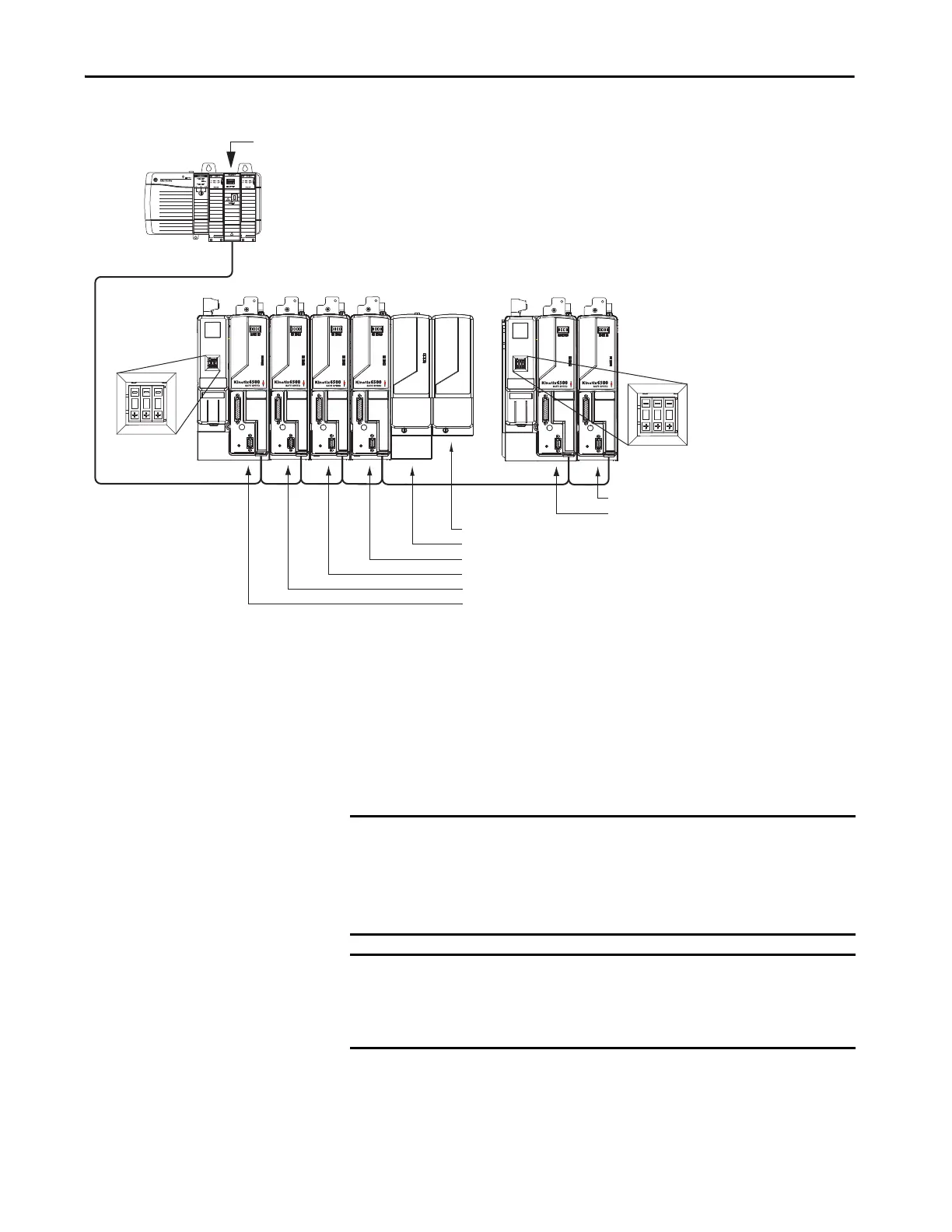
Figure 90 - Node Addressing Example 1
In Example 1, the Kinetix 6500 (6-axis) drive system 1 power rail contains four
control modules, one shunt module, and one slot-filler module. The shunt
module and slot-filler modules are not assigned a IP address, but the system
identifies them with a slot location.
Kinetix 6500 (2-axis) drive system 2 power rail contains two control modules.
The base node address of the (system 2) control module must be set for an
address of ≥007.
Kinetix 6500 Drive
System 2
(2-axis power rail)
192.168.1.6 = Slot-filler module slot location
192.168.1.5 = Shunt module slot location
192.168.1.4 = Control module (AM axis 4) IP address
192.168.1.3 = Control module (AM axis 3) IP address
192.168.1.2 = Control module (AM axis 2) IP address
192.168.1.1 = Control module (IAM axis 1) IP address
ControlLogix Platform
1756-ENxT EtherNet/IP Module
192.168.1.8 = Control module (AM axis 2) IP address
192.168.1.7 = Control module (IAM axis 1) IP address
Kinetix 6500 Drive
System 1
(6-axis power rail)
1595J-M8CBJM-x
Ethernet (shielded) Cable
Base node address
set to 001.
Base node address
set to 007.
IMPORTANT The IP address for each AM (control) module is determined by the base-node
address switch setting on the IAM power module.
Do not position axis modules to the right of shunt or slot-filler modules. The
added distance between non-adjacent axes can increase electrical noise and
impedance, and requires longer fiber-optic cable lengths.
IMPORTANT Slot-filler modules must be used to fill any unoccupied slot on the power
rail; however, you can replace slot-filler modules with AM power modules or
the 2094-BSP2 shunt module (maximum one 2094-BSP2 shunt module per
power rail).

 Loading...


