Rockwell Automation Publication 2094-UM002G-EN-P - August 2016 67
Connector Data and Feature Descriptions Chapter 4
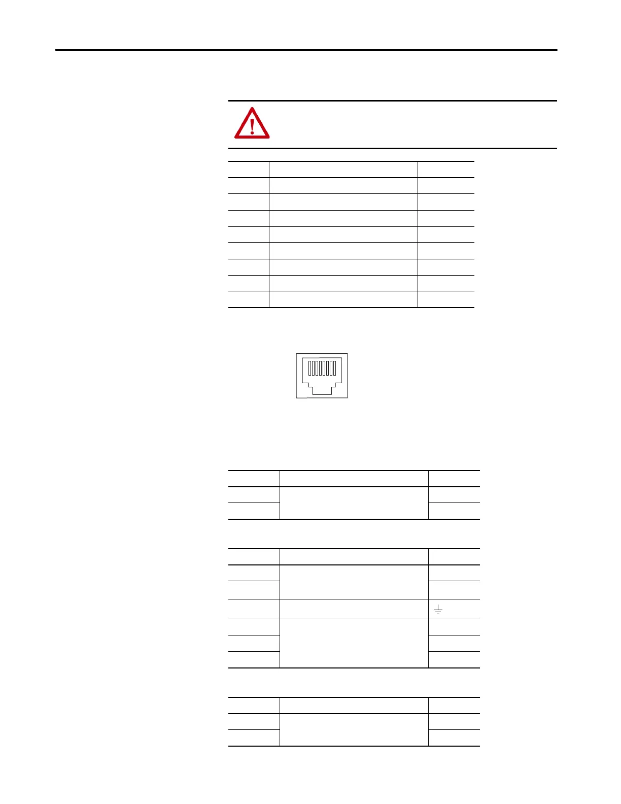
Ethernet Communication Connector Pinout
Figure 32 - Pin Orientation for 8-pin Ethernet PORT1 and PORT2 Connectors
IAM Input Connector Pinout
Table 23 - Control Power Connector
Table 24 - DC Bus and Input Power Connector
Table 25 - Contactor Enable Connector
ATTENTION: To avoid damage to components, determine which power
supply your encoder requires and connect to either the 5V or 9V supply, but
not both.
Pin Description Signal
1 Transmit+ TD+
2 Transmit- TD-
3 Receive+ RD+
4 Reserved —
5 Reserved —
6 Receive- RD-
7 Reserved —
8 Reserved —
CPD Pin Description Signal
1
Control power VAC input
CTRL 2
2CTRL 1
IPD Pin Description Signal
1 An integral, unregulated power supply, consisting
of AC line input, three-phase bridge rectifier, and
filter capacitors.
DC-
2DC+
3 Chassis ground.
4
Three-phase input power.
L3
5L2
6L1
CED Pin Description Signal
1
Relay-driven dry contact used in the control string
for a three-phase power contactor.
CONT EN-
2 CONT EN+

 Loading...


