Rockwell Automation Publication 2094-UM002G-EN-P - August 2016 129
Connect the Kinetix 6200 and Kinetix 6500 Drive System Chapter 5
External Shunt Module
Connections
Follow these guidelines when wiring your external passive shunt module.
Table 83 - Shunt Module Wiring
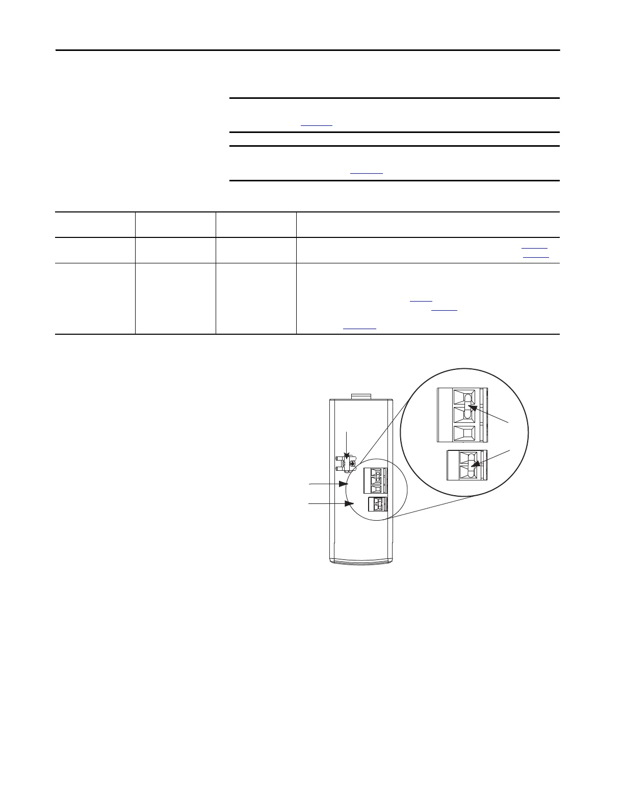
Figure 73 - Shunt Module Jumper Settings
(1) These are the default jumper settings.
IMPORTANT When tightening screws to secure the wires, refer to the tables beginning on
page 103
for torque values.
IMPORTANT To improve system performance, run wires and cables in the wireways as
established in Chapter
2.
Use This
Shunt Module
Cat. No.
With This
Drive Module
Do This
Power rail mounted shunt
module.
2094-BSP2 N/A
• Verify the internal shunt jumper is in place between RC-2 and RC-3 (refer to Figure 73).
• Verify the thermal switch jumper is in place between TS-1 and TS-2 (refer to Figure 73).
External passive shunt
module connected to the
power rail shunt module.
1394-SRxxxx
2094-BSP2
Shunt module
• Remove the internal shunt jumper between RC-2 and RC-3.
• Remove the thermal switch jumper between TS-1 and TS-2
(if your shunt module includes a thermal switch).
• Refer to External Shunt Modules on page 50 for noise zone considerations.
• Refer to Shunt Module Wiring Examples on page 241.
• Refer to the installation instructions provided with your Bulletin 1394 shunt module,
publication 2090-IN004.
1 2 3
1 2
1 2 3
1 2
COL
INT
DC+
TS2
TS1
COL
INT
DC+
TS2
TS1
External Shunt Resistor
(RC) Connector
Kinetix 6000 Shunt Module, Top View
(catalog number 2094-BSP2)
External Thermal Switch
(TS) Connector
Cable Shield
Clamp
Jumpers
(1)

 Loading...


