Rockwell Automation Publication 2094-UM002G-EN-P - August 2016 225
Remove and Replace the Kinetix 6200 and Kinetix 6500 Drive Modules Chapter 9
Remove the Control Module
You can remove the control module from the power module (to replace the
control module) or you can remove the control module and power module as a
single unit, for example, to move an axis to another slot on the power rail. To
remove the control module and power module as a single unit, refer to Remove
the Drive Modules on page 226
.
This procedure assumes that you are starting with the Kinetix 6200 or
Kinetix 6500 drive system mounted on the power rail.
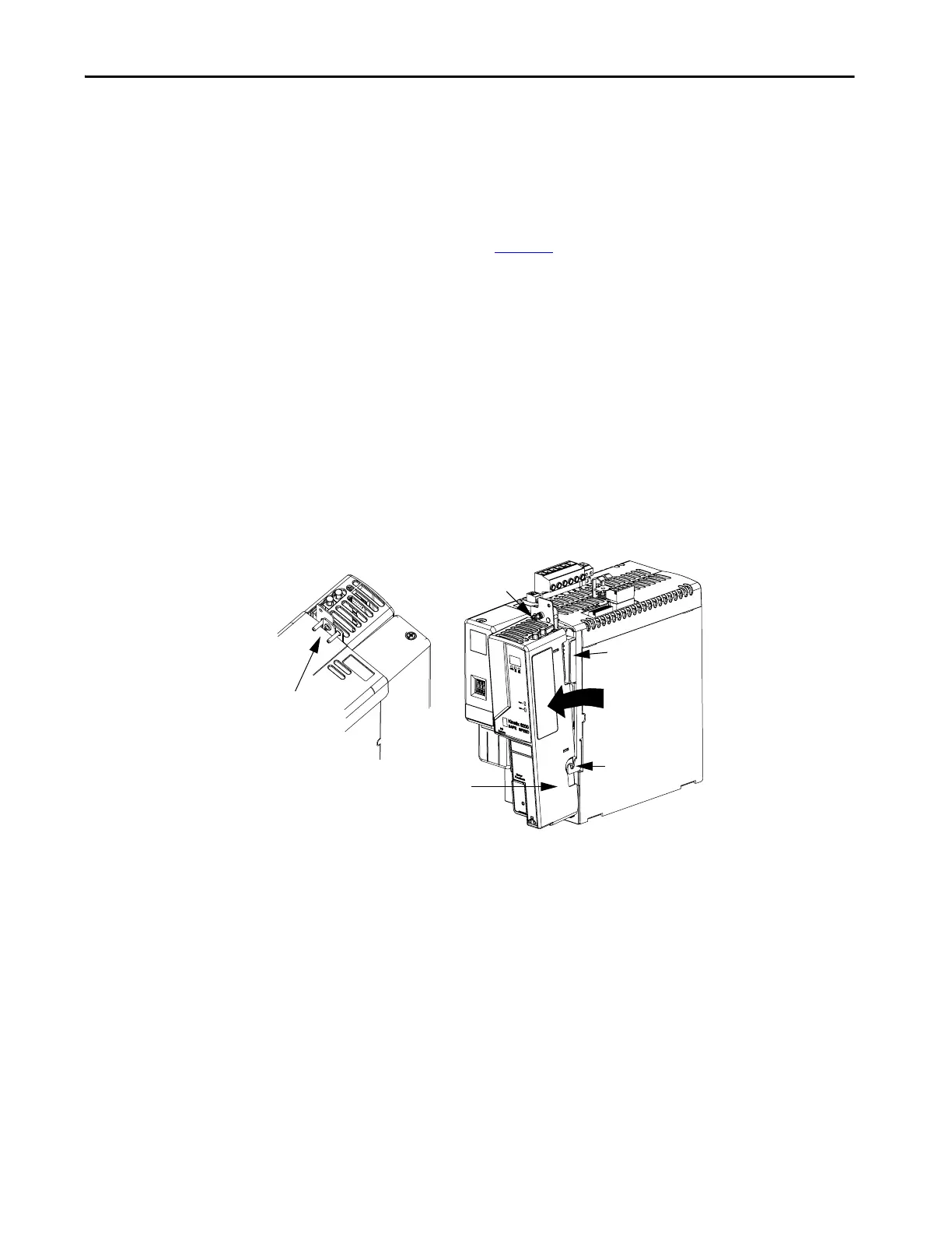
Follow these steps to remove the control module.
1. Loosen the captive screw on top of the control module.
2. Grasp the control module and power module, and gently pull the
control module away from the connectors enough to clear the guide
pins.
The control module mounting studs pivot on the hooks.
3. Lift the control module off of the hooks and remove the control module
from the power module.
Bulletin 2094
Control Module
Mounting Stud
and Hook
Control Module
Pulling Away From
Signal Connector
Guide Pin Alignment
Bulletin 2094 IAM or
AM Power Module
(IAM power module is shown)
Captive Screw

 Loading...


