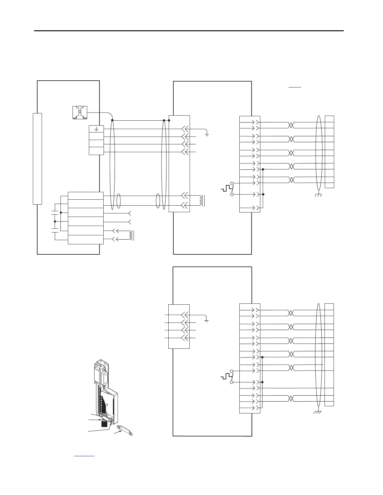
EasyManuals Logo
Home>Allen-Bradley>Servo Drives>Kinetix 6200

Allen-Bradley Kinetix 6200 User Manual

Allen-Bradley Kinetix 6200
336 pages
To Next Page IconTo Next Page
To Previous Page IconTo Previous Page
Page #247 background imageLoading...
Page #247 background image
Rockwell Automation Publication 2094-UM002G-EN-P - August 2016 247
Interconnect Diagrams Appendix A
Axis Module/Linear Motor/
Actuator Wiring Examples
These examples apply to Kinetix 6200 and Kinetix 6500 drives with
Allen-Bradley linear motors and actuators.
Figure 107 - AM Module with MP-Series Integrated Linear Stages
D
C
B
A
BR+
BR-
F
G
W
V
U
SIN+
SIN-
COS+
COS-
DATA+
DATA-
+5VDC
ECOM
GREEN
WHITE/GREEN
GRAY
WHITE/GRAY
BLACK
WHITE/BLACK
RED
WHITE/RED
3
4
5
6
1
2
9
10
1
2
3
4
5
10
14
6
14
12
+9VDC
TS
ORANGE
WHITE/ORANGE
11
13
7
11
4
3
2
1
6
5
4
3
2
1
Green/Yellow
Blue
Black
Brown
Black
White
GND
W
V
U
GND
Shield
W
V
U
MBRK -
MBRK +
COM
PWR
DBRK -
DBRK +
BR+
BR-
D
C
B
A
COM
AM+
AM-
BM+
BM-
IM+
IM-
+5VDC
ECOM
WHITE/BLUE
GREEN
WHITE/GREEN
GRAY
WHITE/GRAY
BLACK
WHITE/BLACK
RED
WHITE/RED
1
2
3
4
5
10
14
6
12
S1
–
TS
ORANGE
WHITE/ORANGE
11
S2
S3
YELLOW
WHITE/YELLOW
13
8
3
4
5
6
1
2
14
15
16
17
12
11
13
9
10
COM
1
2
3
4
5
6
7
8
9
10
11
12
13
14
15
Motor Brake
Resistive Brake
Connections
Motor/Resistive
Brake (BC) Connector
Motor Power
(MP) Connector
Cable Shield
Clamp
Note 10
Note 15
MPAS-Bxxxxx-VxxSxA
Ballscrew Linear Stages
with
High Resolution Feedback
Motor Feedback
(MF) Connector
Three-phase
Motor Power
Motor
Feedback
Thermostat
User Supplied
24V DC
Three-phase
Motor Power
Motor
Feedback
Thermostat
MPAS-Bxxxxx-ALMx2C
Direct Drive Linear Stages
with
Incremental Feedback
Refer to low-profile connector
illustration (lower left)
for proper grounding technique.
Refer to low-profile connector
illustration (lower left)
for proper grounding technique.
Grounding Technique for
Feedback Cable Shield
Turn clamp over to hold
small cables secure.
Exposed shield secured
under clamp.
Clamp Screws (2)
Clamp
Refer to table on page 232
for note information.
2090-CFBM7DF-CEAAxx (standard) or
2090-CFBM7DF-CEAFxx (continuous-flex)
(flying-lead) Feedback Cable
Notes 16, 19
2090-XXNFMF-Sxx (standard) or
2090-CFBM7DF-CDAFxx (continuous-flex)
(flying-lead) Feedback Cable
Note 16
2090-CPxM7DF-16AAxx
(standard)
or 2090-CPxM7DF-16AFxx
(continuous-flex) Power Cable
Note 16
IAM (inverter) or AM
Power Module
2090-K6CK-D15M
Connector Kit
2090-K6CK-D15M
Low-profile Connector Kit
2090-K6CK-D15M
Connector Kit
Refer to Low Profile Connector Kit Installation Instructions,
publication 2094-IN007
, for connector kit specifications.
2090-CPWM7DF- 16AAxx
(standard)
or 2090-CPWM7DF-16AFxx
(continuous-flex) Power Cable
Note 16

Table of Contents

Other manuals for Allen-Bradley Kinetix 6200

Questions and Answers:

Question and Answer IconNeed help?

Do you have a question about the Allen-Bradley Kinetix 6200 and is the answer not in the manual?

Allen-Bradley Kinetix 6200 Specifications

General IconGeneral
BrandAllen-Bradley
ModelKinetix 6200
CategoryServo Drives
LanguageEnglish

Related product manuals