62 Rockwell Automation Publication 2094-UM002G-EN-P - August 2016
Chapter 4 Connector Data and Feature Descriptions
2094 Power Module and
Control Module Features
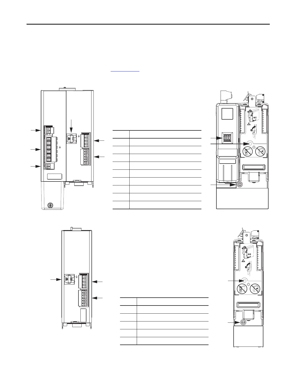
Use these illustrations to identify the connectors and indicators for the
IAM/AM power modules and control modules. Sercos interface and Ethernet
network connectors for the Kinetix 6000M IPIM module are also shown. For
the remainder of the IPIM module features and indicators, refer to the
Kinetix 6000M Integrated Drive-Motor System User Manual, publication
2094-UM003
.
Figure 26 - IAM Power Module Features and Indicators
Figure 27 - AM Power Module Features and Indicators
1 2
DC-
DC+
L3
L2
L1
CONT EN-
CONT EN+
CTRL 2
CTRL 1
1 2
1 2 3 4 5 6
W
V
U
MBRK -
MBRK +
COM
PWR
DBRK -
DBRK +
1 2 3 4
1 2 3 4 5 6
1
4
5
2
3
6
7
9
8
Kinetix 6200 or Kinetix 6500
IAM Power Module, Top View
(2094-BC01-MP5-M is shown)
Kinetix 6200 or Kinetix 6500
IAM Power Module, Front View
(2094-BC01-MP5-M is shown)
Item Description
1 Control power (CPD) connector
2 DC bus/AC input power (IPD) connector
3 Contactor enable (CED) connector
4 Motor cable shield clamp
5 Motor power (MP) connector
6 Motor/resistive brake (BC) connector
7 Node address switch
8 Power-applied indicator
9Mounting screw
W
V
U
MBRK -
MBRK +
COM
PWR
DBRK -
DBRK +
1 2 3 4
1 2 3 4 5 6
1
2
3
5
4
Kinetix 6200 or Kinetix 6500
AM Power Module, Top View
(2094-BMP5-M is shown)
Kinetix 6200 or Kinetix 6500
AM Power Module, Front View
(2094-BMP5-M is shown)
Item Description
1 Motor cable shield clamp
2 Motor power (MP) connector
3 Motor/resistive brake (BC) connector
4 Power-applied indicator
5Mounting screw

 Loading...


