Rockwell Automation Publication 2094-UM002G-EN-P - August 2016 241
Interconnect Diagrams Appendix A
Shunt Module Wiring Examples
Refer to Kinetix Motion Accessories Technical Data, publication KNX-
TD004 for the Bulletin 1394 external shunt module catalog numbers available
for the Kinetix 6200 and Kinetix 6500 drive systems.
Figure 100 - Shunt Module Wired for Internal Operation (default configuration)
Refer to the Kinetix 6000 Shunt Module Installation Instructions, publication
2094-IN004
, for additional installation information.
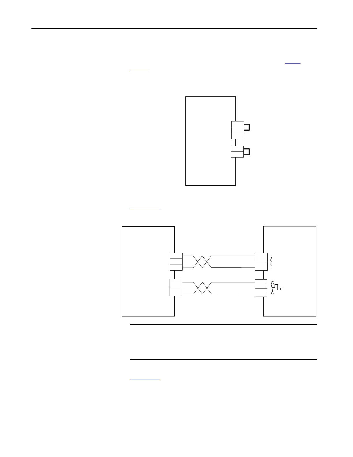
Figure 101 - Shunt Module with External Passive Shunt
Refer to the External Shunt Module Installation Instructions, publication
2090-IN004
, for additional installation information.
2094-BSP2
Kinetix 6000
Shunt Module
External Shunt Resistor
(RC) Connector
External Thermal Switch
(TS) Connector
COL
INT
DC+
2
1
3
2
1
TS2
TS1
COL
DC+
2094-BSP2
Kinetix 6000
Shunt Module
Bulletin 1394
External Passive
Shunt Module
External Shunt Resistor
(RC) Connector
External Thermal Switch
(TS) Connector
Resistor
Thermal
Switch
IMPORTANT Only passive shunts with a thermal switch are wired to the TS connector on
the Kinetix 6000 shunt module. If your external passive shunt does not have
a thermal switch, leave the jumper (default configuration) in place on the TS
connector.

 Loading...


