66 Rockwell Automation Publication 2094-UM002G-EN-P - August 2016
Chapter 4 Connector Data and Feature Descriptions
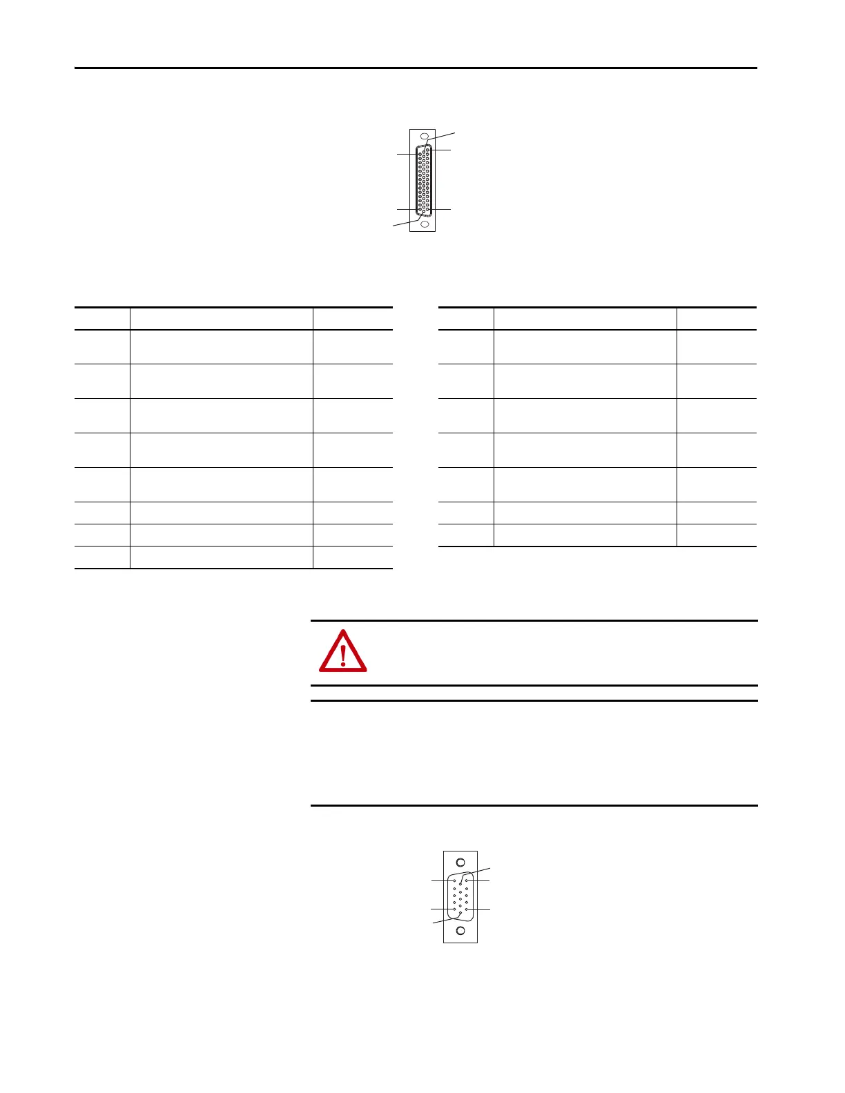
Figure 30 - Pin Orientation for 44-pin I/O, Safety, and Auxiliary Feedback (IOD) Connector
Motor Feedback Connector Pinout
Figure 31 - Pin Orientation for 15-pin Motor Feedback (MF) Connector
Pin 30
Pin 44
Pin 1
Pin 15
Pin 16
Pin 31
MF Pin Description Signal MF Pin Description Signal
1
Sine differential input +
A differential input +
MTR_SIN+
MTR_AM+
9 Clock output + MTR_CLK+
2
Sine differential input -
A differential input -
MTR_SIN-
MTR_AM-
10
Data differential input/output -
Index differential input -
MTR_DATA-
MTR_IM-
3
Cosine differential input +
B differential input +
MTR_COS+
MTR_BM+
11 Motor thermostat (normally closed)
(2)
MTR_TS
4
Cosine differential input -
B differential input -
MTR_COS-
MTR_BM-
12 Hall commutation S1 input MTR_S1
5
Data differential input/output +
Index differential input +
MTR_DATA+
MTR_IM+
13 Hall commutation S2 input MTR_S2
6 Encoder common MTR_ECOM 14 Encoder 5V power output MTR_EPWR5V
(1)
7 Encoder 9V power output MTR_EPWR9V
(1)
15 Clock output - MTR_CLK-
8 Hall commutation S3 input MTR_S3
(1) Determine which power supply your encoder requires and connect to only the specified supply. Do not make connections to both.
(2) Not applicable unless motor has integrated thermal protection. Common (TS-) signal for thermal switch is tied to MF-6 (ECOM) in Bulletin 2090 cables.
ATTENTION: To avoid damage to components, determine which power
supply your encoder requires and connect to either the 5V or 9V supply, but
not both.
IMPORTANT Combined motor-power cable length for all axes on the same DC bus must
not exceed 240 m (787 ft) with 460V systems. Drive-to-motor power cables
must not exceed 90 m (295.5 ft).
System performance was tested at these cable length specifications. These
limitations also apply when meeting CE requirements.
Pin 11
Pin 6
Pin 15
Pin 1
Pin 10
Pin 5

 Loading...


