224 Rockwell Automation Publication 2094-UM002G-EN-P - August 2016
Chapter 9 Remove and Replace the Kinetix 6200 and Kinetix 6500 Drive Modules
Remove Kinetix 6200 and
Kinetix 6500 Drive Modules
Follow these steps to remove the control modules, power modules, IPIM,
shunt, and slot-filler modules from the Bulletin 2094 power rail.
1. Verify that all control and input power has been removed from the
system.
2. Wait five minutes for the DC bus to discharge completely before
proceeding.
3. Label and remove all connectors from the IAM/AM module you are
removing.
To identify each connector, refer to page 62
.
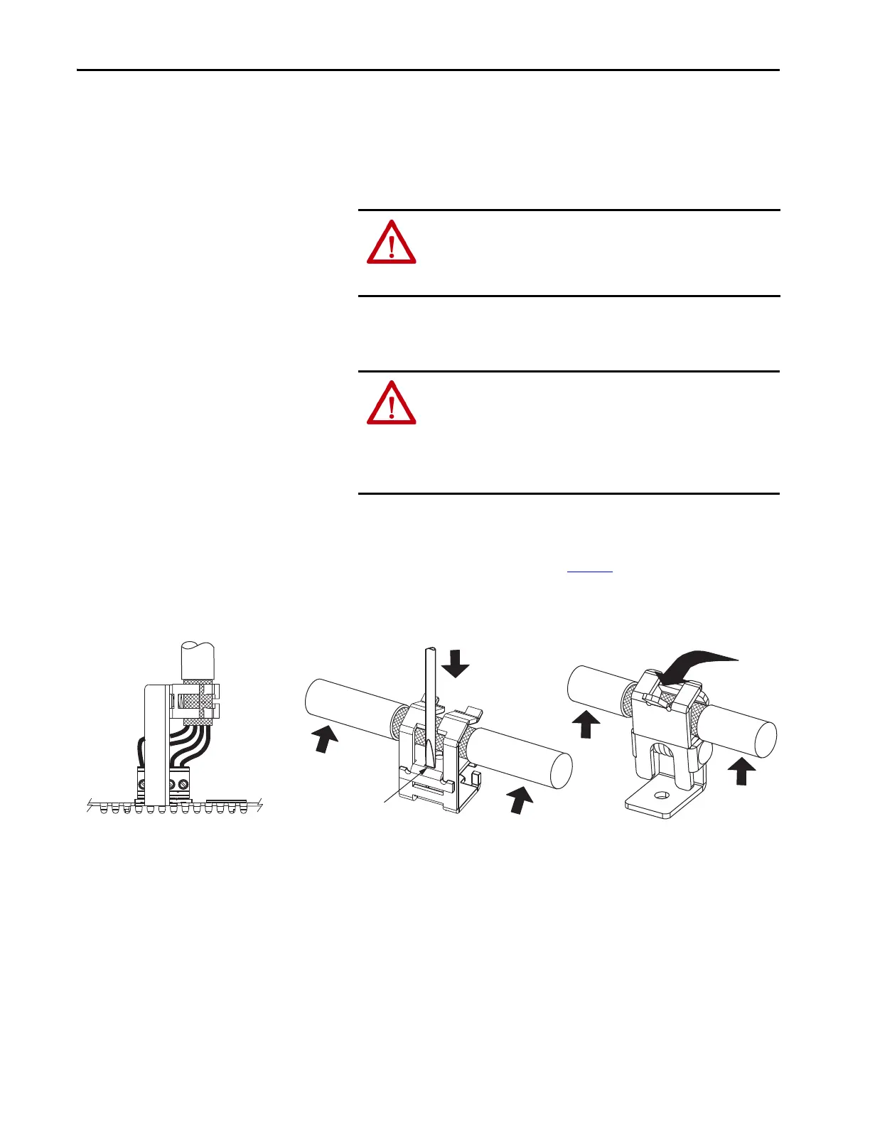
4. Remove the motor cable from the cable shield clamp, as shown in these
examples.
ATTENTION: To avoid shock hazard or personal injury, assure that all
power has been removed before proceeding. This system can have
multiple sources of power. More than one disconnect switch can be
required to de-energize the system.
ATTENTION: This product contains stored energy devices. To avoid
hazard of electrical shock, verify that all voltage on capacitors has
been discharged before attempting to service, repair, or remove this
unit. Do not attempt the procedures in this document unless you are
qualified to do so and are familiar with solid-state control
equipment and the safety procedures in publication NFPA 70E.
Use screwdriver with
3.5 mm (0.14 in.) tip to depress
spring and remove cable.
Slide-open
Cable Clamp
Screwdriver Tip in Slot
Vertical Cable Clamp
Orientation Example
Cable Clamp
Motor
Cable
Vent Holes on Top of IAM/AM Module
Horizontal Cable Clamp
Orientation Examples
Pivot-open
Cable Clamp
Pry back
with thumb.

 Loading...


