Rockwell Automation Publication 2094-UM002G-EN-P - August 2016 55
Mount the Kinetix 6200 and Kinetix 6500 Drive System Chapter 3
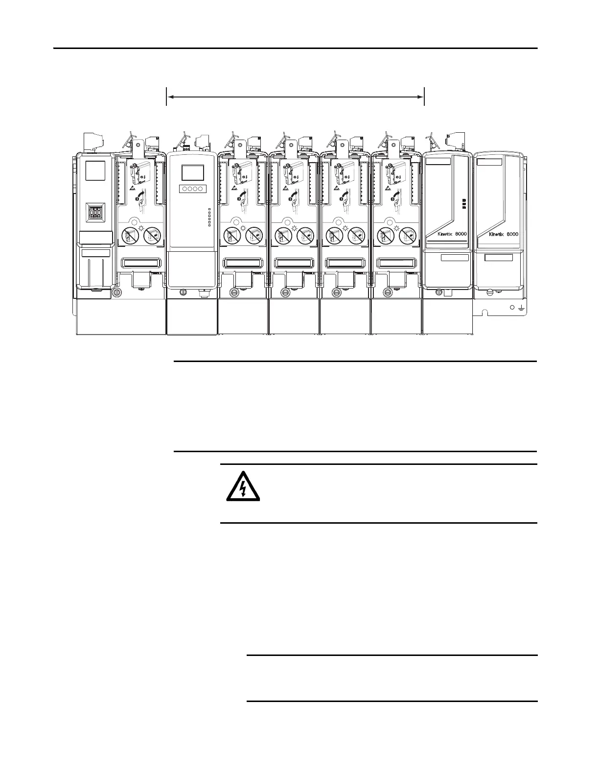
Figure 25 - Module Mounting Order Example
Mount Modules on the
Power Rail
Follow these steps to mount the IAM, AM, IPIM, shunt, and slot-filler
modules.
1. Remove the protective covers from the power rail connectors.
Highest Power Utilization
Lowest Power Utilization
Integrated Axis Module
2094-BC02-M02-M
IPIM Module
2094-SEPM-B24-S
Axis Module
2094-BM01-M
Axis Module
2094-BM01-M
Axis Module
2094-BMP5-M
Axis Module
2094-BMP5-M
Shunt Module
2094-BSP2
Slot-filler Module
2094-PRF
IMPORTANT The IAM module must be positioned in the leftmost slot of the power rail. Position your
AM/IPIM modules, shunt module, and slot-filler modules to the right of the IAM module.
The shunt module must be installed to the right of the last AM/IPIM module. Only slot-
filler modules can be installed to the right of the shunt module.
Do not mount the shunt module on power rails with a follower IAM module. Common-bus
follower IAM modules disable the internal, rail mounted, and external shunt modules.
SHOCK HAZARD: To avoid personal injury due to electrical shock, place a
2094-PRF slot-filler module in all empty slots on the power rail. Any power
rail connector without a module installed disables the Bulletin 2094 system;
however, control power is still present.
TIP All modules mount to the power rail by using the same technique; however,
only the IAM module is used in the examples.
IMPORTANT The IAM module must be positioned in the leftmost slot of the
power rail. Position your axis modules, shunt module, and slot-filler
modules to the right of the IAM module.

 Loading...


