68 Rockwell Automation Publication 2094-UM002G-EN-P - August 2016
Chapter 4 Connector Data and Feature Descriptions
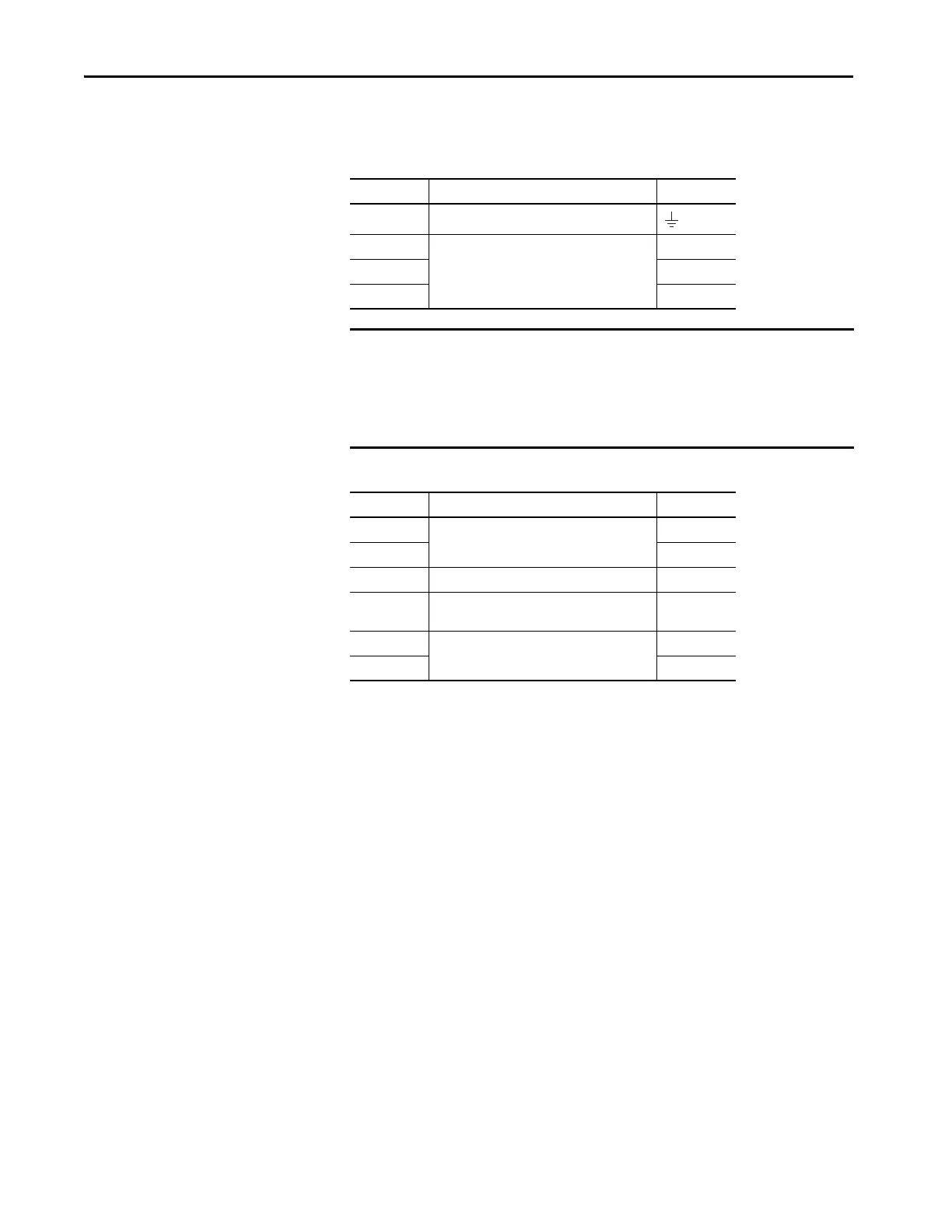
IAM and AM Motor Power and Brake Connector Pinout
Table 26 - Motor Power Connector
Table 27 - Motor Brake/Resistive Brake Connector
MP Pin Description Signal
4 Chassis ground
3
Three-phase motor power
W
2V
1U
IMPORTANT Combined motor-power cable length for all axes on the same DC bus must
not exceed 240 m (787 ft) with 460V systems. Drive-to-motor power cables
must not exceed 90 m (295.5 ft).
System performance was tested at these cable length specifications. These
limitations also apply when meeting CE requirements.
BC Pin Description Signal
6
Motor brake connections
MBRK-
5MBRK+
4 Motor brake common COM
3
+24V brake input power
(from LIM module or customer supplied)
PWR
2
RBM module connections
(from RBM module and safety string)
DBRK-
1DBRK+

 Loading...


