210 Rockwell Automation Publication 2094-UM002G-EN-P - August 2016
Chapter 8 Troubleshoot the Kinetix 6200 and Kinetix 6500 Drive System
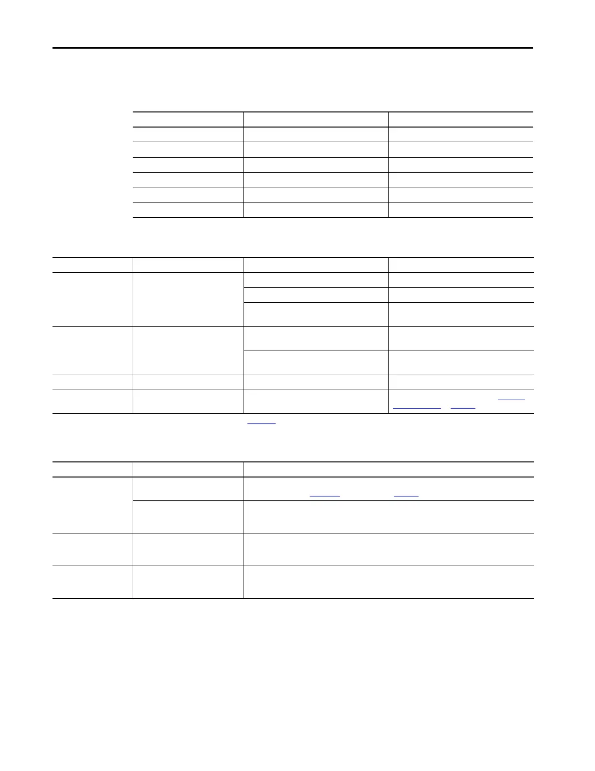
Control Module Status Indicators
Table 94 - Drive Status Indicator (sercos control modules)
Table 95 - Comm Status Indicator (sercos control modules)
Table 96 - Bus Status Indicator
Condition Drive Status Possible Resolution
Off No power Apply power.
Alternating green/red Self-test (power-up diagnostics) Wait for steady green.
Flashing green
(1)
Standby (device not configured) Wait for steady green.
Steady green Normal operation, no faults N/A
Flashing red Minor fault (recoverable) Refer to four-character fault message.
Steady red Major fault (non-recoverable) Refer to four-character fault message.
(1) This condition is the same as sercos ring phases 0, 1, 2, and 3.
Condition Drive Status Potential Cause Possible Resolution
Off No communication
(1)
Loose fiber-optic connection. Verify proper fiber-optic cable connections.
Broken fiber-optic cable. Replace fiber-optic cable.
Receive fiber-optic cable connected to sercos
transmit connector and vice versa.
Check proper sercos fiber-optic cable connections.
Flashing green
(2)
Establishing communication
System is still in the process of establishing sercos
communication.
Wait for steady green indicator.
Node address setting on the drive module does not
match sercos controller configuration.
Verify proper node switch setting.
Steady green Communication ready No faults or failures. N/A
Steady red No communication Duplicate node address
Verify proper node addressing. Refer to Configure
the Drive Modules on page 169.
(1) Refer to Fiber-optic Cable Installation and Handling Instructions, publication 2090-IN010, for more information.
(2) This condition is the same as sercos ring phases 1, 2, and 3.
Condition Bus Status Condition
Off
No power or DC bus is not present.
• Normal when bus power is not applied.
• Fault exists, refer to Fault Codes troubleshooting on page 200.
Bus power is present in follower IAM.
• Follower IAM power module is not configured as CommonBus Follow in Logix Designer application.
• After DC bus voltage is applied, a 2.5 second delay before the indicator begins flashing green is normal
operation to provide the common-bus leader module time to complete pre-charge.
Flashing green
Bus power is present, axis disabled.
No major faults.
Normal when:
• 24V is not applied to Hardware Enable Input.
• MSO instruction is not commanded in the Logix Designer application.
Steady green
Bus power is present, axis enabled.
No major faults.
Normal when:
• 24V is applied to Hardware Enable Input.
• MSO instruction is commanded in the Logix Designer application.

 Loading...


