Rockwell Automation Publication 2094-UM002G-EN-P - August 2016 65
Connector Data and Feature Descriptions Chapter 4
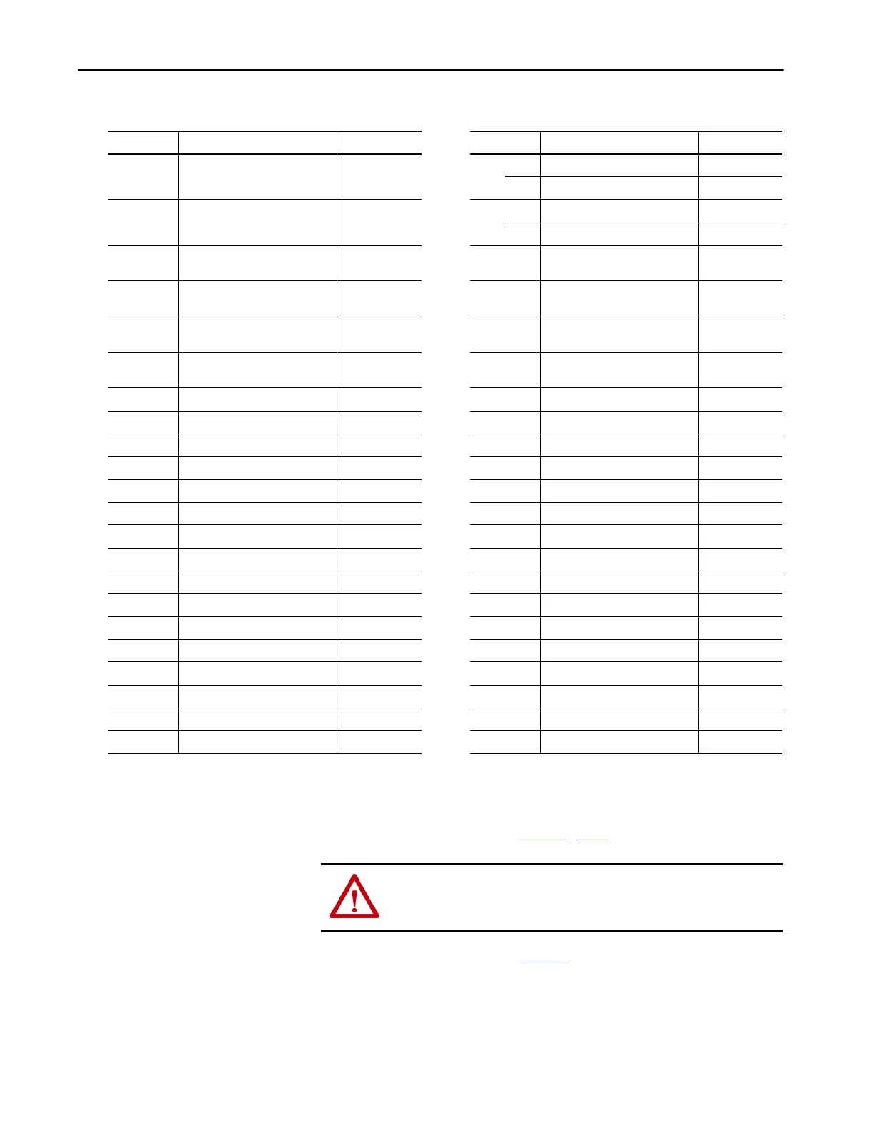
I/O, Safety, and Auxiliary Feedback Connector Pinout
Refer to Additional Resources on page 12 for links to Kinetix 6200 and
Kinetix 6500 safety reference manuals.
IOD Pin
(1)
Description Signal IOD Pin
(1)
Description Signal
1
Sine differential input +
A differential input +
AUX_SIN+
AUX_A+
23
(S52) Safe limited speed input 0 SLS_IN_CH0
Safe stop input 2 SS_IN_CH2
(3)
2
Sine differential input -
A differential input -
AUX_SIN-
AUX_A-
24
(S62) Safe limited speed input 1 SLS_IN_CH1
Safe stop input 3 SS_IN_CH3
(3)
3
Cosine differential input +
B differential input +
AUX_COS+
AUX_B+
25 Reset reference RESET_REF
4
Cosine differential input -
B differential input -
AUX_COS-
AUX_B-
26 (S34) Reset input RESET_IN
5
Data differential input +
Index differential input +
AUX_DATA+
AUX_I+
27 (S11) Pulse test output 0 TEST_OUT_0
6
Data differential input -
Index differential input -
AUX_DATA-
AUX_I-
28 (S21) Pulse test output 1 TEST_OUT_1
7 Clock output + AUX_CLK+ 29 (68) Safe limited speed output 0 SLS_OUT_CH0
8Clock output - AUX_CLK- 30 (78)Safe limited speed output 1 SLS_OUT_CH1
9 Encoder 5V power output EPWR5V
(2)
31 (S32) Door monitor input 0 DM_IN_CH0
10 Encoder common ECOM 32 (S42) Door monitor input 1 DM_IN_CH1
11 Encoder 9V power output EPWR9V
(2)
33 (X32) Lock monitor input 0 LM_IN_CH0
12 Reserved – 34 (X42) Lock monitor input 1 LM_IN_CH1
13 Reserved – 35 (51) Door control channel output- DC_OUT_CH0
14 24V power out 24VPWR
(3)
36 (52) Door control channel output+ DC_OUT_CH1
15 24V common 24VCOM
(3)
37 (S72) Enabling switch monitor input 0 ESM_IN_CH0
16 Reserved – 38 (S82) Enabling switch monitor input 1 ESM_IN_CH1
17 (A1) Safety 24V power input SPWR 39 24V power out 24VPWR
(4)
18 (A2) Safety 24V common SCOM 40 24V common 24VCOM
(4)
19 (S12) Safe stop input 0 SS_IN_CH0 41 Digital input 1 (drive enable) INPUT1
(5)
20 (S22) Safe stop input 1 SS_IN_CH1 42 Digital input 2 (home) INPUT2
(5)
21 (34) Safe stop output 0 SS_OUT_CH0 43 Digital input 3 (registration 1) INPUT3
(5)
22 (44) Safe stop output 1 SS_OUT_CH1 44 Digital input 4 (registration 2) INPUT4
(5)
(1) Designators in parenthesis refer to the Guardmaster® MSR57P safety relay and PowerFlex® 750-Series safety option terminals.
(2) Determine which power supply your encoder requires and connect to only the specified supply. Do not make connections to both.
(3) This signal applies to only the 2094-SE02F-M00-S0 and 2094-EN02D-M01-S0 control modules. Use this supply to power the Safety 24V (SPWR/SCOM) input. Do not connect this 24V supply
to any external safety device.
(4) Use signals 24VPWR and 24VCOM (IOD-39 and IOD-40) as a 24V DC source to operate the digital inputs (50 mA maximum per input).
(5) Default assignments are in parenthesis. Use sercos IDN Write instruction to change default assignments. Refer to Digital Inputs
on page 69 for more information.
ATTENTION: To avoid damage to components, determine which power
supply your encoder requires and connect to either the 5V or 9V supply, but
not both.

 Loading...


