Rockwell Automation Publication 2094-UM002G-EN-P - August 2016 125
Connect the Kinetix 6200 and Kinetix 6500 Drive System Chapter 5
Connect Panel-mounted Breakout Board Kits
The 2090-UXBK-D15xx panel-mounted breakout board kit includes a DIN-
rail breakout board and cable. The cable connects between the breakout board
and the motor feedback (MF) connector. Wires from your flying-lead motor
feedback cable connect to the terminals.
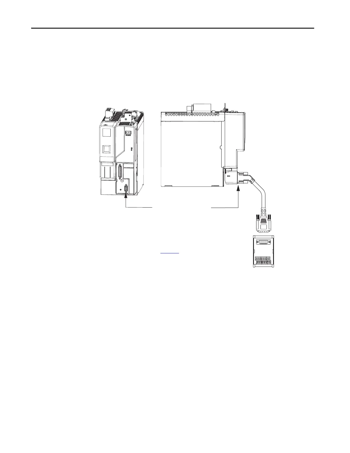
Figure 67 - IAM/AM Power Module/Control Module (MF connector)
2090-UXBC-D15xx
Breakout Cable
2090-UXBB-D15
Panel-mounted Breakout Board
Wire Terminations
Motor Feedback (MF) Connector
Kinetix 6200 or Kinetix 6500, Front View
(IAM power module with
control module is shown)
Kinetix 6200 or Kinetix 6500, Side View
(IAM power module with
control module is shown)
Refer to CN2 Motor Feedback Breakout Board
Installation Instructions, publication 2090-IN006
, for
connector specifications.

 Loading...


