 Loading...
Do you have a question about the GE Voluson P6 BT16 and is the answer not in the manual?
| Brand | GE |
|---|---|
| Model | Voluson P6 BT16 |
| Category | Medical Equipment |
| Language | English |
Provides a summary of the manual's content and essential warnings for servicing.
Details important conventions, including model designations, icons, and safety precaution messages.
Outlines critical safety precautions for operation, service, and repair of the equipment.
Explains electromagnetic compatibility and compliance requirements for the system.
Provides contact information for technical support and additional assistance.
Introduces the chapter's purpose, covering facility and electrical needs for installation.
Details environmental, electrical, and cooling requirements for system installation.
Outlines purchaser responsibilities and mandatory site requirements for installation.
Provides a summary of setup procedures, including receiving, unpacking, and configuring the equipment.
Offers reminders and information on average installation time and warnings.
Details procedures for receiving, inspecting, and unpacking the system and peripherals.
Covers customer order verification and system component inspection before setup.
Provides instructions for connecting various auxiliary devices and peripherals to the system.
Details procedures for connecting the unit to power and the initial boot-up process.
Covers the installation procedures for different types of printers.
Provides instructions for installing the cellular modem kit.
Guides through system setup, parameter modifications, and configuration options.
Explains communication and connection options for the ultrasound unit.
Details TCP/IP and wireless network configuration procedures.
Introduces the chapter's purpose, which is to check major system functions and diagnostics.
Lists necessary items for performing functional checks, including media and transducers.
Outlines general procedures for system power on/off and safety considerations.
Details basic functional checks for system modes and features.
Covers procedures for saving and loading system configurations and images.
Describes checks for system setup, general settings, administration, and connectivity.
Details checks for peripherals like printers, ECG, and network adapters.
Explains how to transition between different operating modes like B Mode, M Mode, and Doppler.
Provides an overview of the system's concepts, component arrangement, and subsystem functions.
Describes the system's capabilities, major components, and internal electronics.
Details the components and block diagram of the Front End Processor.
Details the components and block diagram of the Back End Processor.
Illustrates the internal input/output connections of the system.
Describes the OPIO subassemblies and functional components of the user interface.
Provides information about the LCD Monitor component.
Explains how to adjust the monitor settings through the utility page.
Details the external input/output connectors on the system.
Lists and describes the various peripherals supported by the system.
Explains the power distribution system and its primary power module.
Describes the InSite Exc system for remote diagnostics and service.
Details the Common Service Desktop software modules and access levels.
Contains specific software/hardware test modules, system setup, and update procedures.
Explains the functions available on the boot screen and LINUX maintenance system.
Describes how to access frequently used tools via the Windows Start Menu.
Details the Voluson Maintenance System with improved service functionality.
Describes how to test and adjust mechanical capabilities that may be out of specification.
Ensures compliance with national regulatory information and tests.
Provides instructions for adjusting the LCD monitor settings.
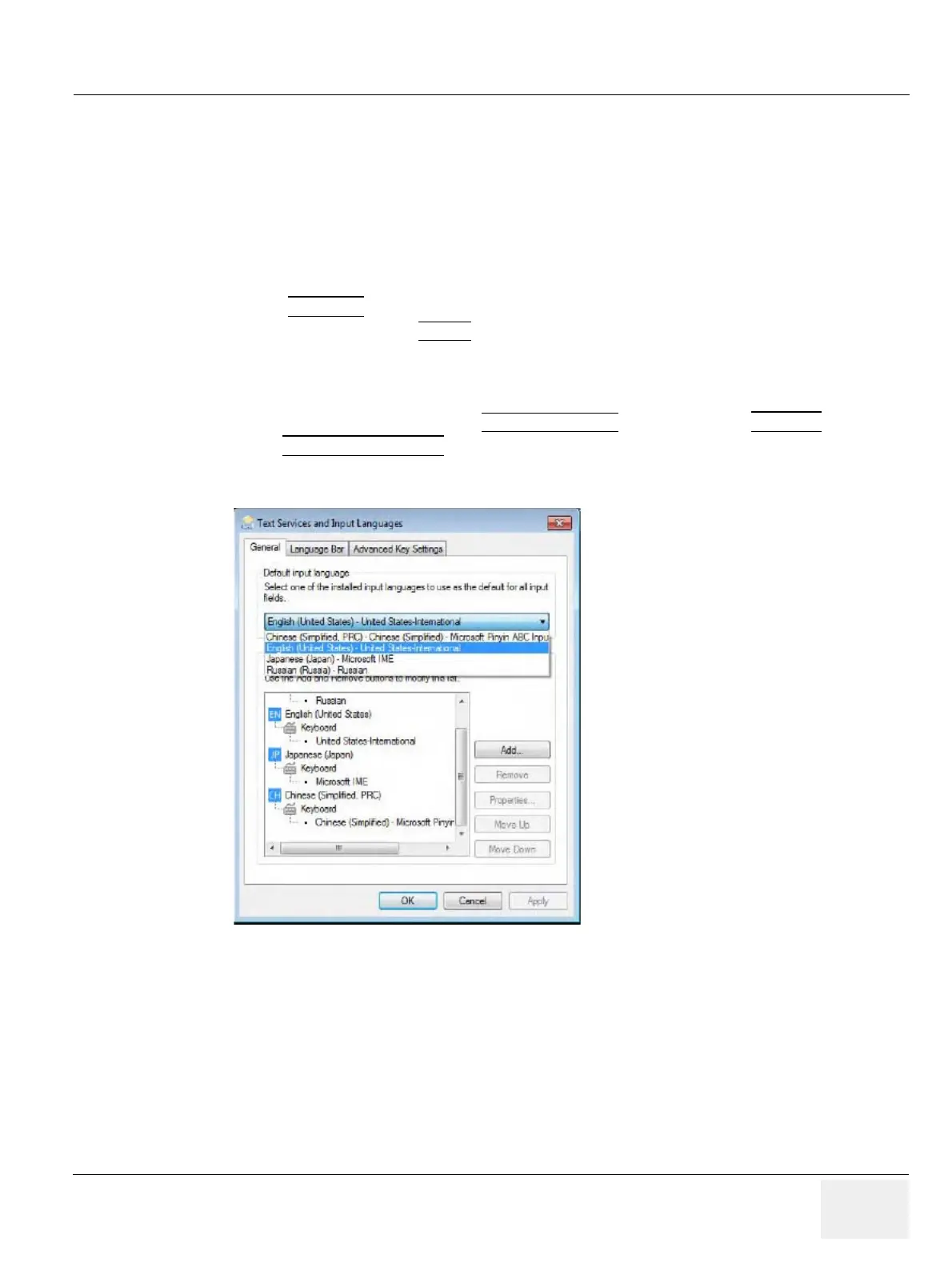
Guides on changing keyboard layout and configuring keys.
Introduces procedures for maintaining image quality and system operation through diagnostics.
Details how to gather essential system data for analysis and reporting malfunctions.
Describes how to check power supply voltages on the backplane.
Explains how to capture screen presentations and network logs for analysis.
Provides capabilities for GE technicians to access and manage customer systems remotely.
Guides on using the Auto Tester program for automated diagnostics.
Details procedures for performing automatic and manual diagnostic tests on hardware components.
Outlines the minimum configuration required to boot and scan the system.
Addresses common issues related to the console and user interface functionality.
Provides guides for common troubleshooting scenarios and helpful technical tips.
Lists common error messages, their reasons, and suggested actions.
Provides an overview of replacement procedures for system modules and subsystems.
Details procedures for installing or upgrading system software via DVD or InSite.
Covers procedures for loading only image settings and presets.
Details procedures for loading a full system backup.
Covers procedures for loading the image archive.
Explains how to replace or activate various software options.
Provides steps for replacing the front cabinet bezel assembly.
Details the procedure for replacing the front DVD plastic bezel assembly.
Provides steps for replacing the front printer bezel assembly.
Details the procedure for replacing the top cabinet cover plastic.
Provides steps for replacing the front pedestal cover.
Details the procedure for replacing the tray pedestal cabinet plastic.
Provides steps for replacing the rear cabinet bezel assembly.
Details the procedure for replacing the encoder set.
Provides steps for replacing the power ON/OFF key PCB assembly.
Details the procedure for replacing the top keyboard assembly.
Provides steps for replacing the OPIO button set.
Details the procedure for replacing the OPIO plastic lower cover assembly.
Provides steps for replacing the OPIO plastic upper cover assembly.
Details the procedure for replacing the monitor.
Provides steps for replacing the monitor arm.
Details the procedure for replacing the LCD cable.
Provides steps for replacing the bumper base rubber assembly.
Details the procedure for replacing the OPIO component.
Provides steps for replacing the speaker.
Details the procedure for removing the pedestal bottom cover.
Provides steps for replacing the NEST.
Details the procedure for replacing the air filter.
Provides steps for replacing the probe holder kit.
Details the procedure for replacing the left side cover assembly.
Provides steps for replacing the right side cover assembly.
Details the procedure for replacing the trackball.
Provides steps for replacing the TGC board.
Details the procedure for replacing the AN keyboard assembly.
Provides steps for replacing the caster cap.
Details the procedure for replacing the caster.
Provides steps for replacing the side cabinet tray.
Details the procedure for replacing the rear handle.
Provides steps for replacing the speaker cover.
Details the procedure for replacing the DPS/DPS with battery.
Provides steps for replacing the DRFM.
Details the procedure for replacing the SOM in the DRFM.
Provides steps for replacing the HDD in the DRFM.
Details the procedure for replacing the DBM64.
Provides steps for replacing the T-DPI.
Details the procedure for replacing the CSI.
Provides steps for replacing the CBP.
Details the procedure for replacing the DVD.
Provides steps for replacing the OPIO USB Sub PWA.
Details the procedure for replacing the AN key top.
Guides on replacing optional peripherals like printers and adapters.
Provides steps for replacing the fan with cable assembly.
Outlines functional checks to be performed after FRU replacement.
Details the procedure for replacing the UVC part.
Provides steps for replacing the CWD piggy.
Details the procedure for replacing the ECG kit assembly.
Provides steps for replacing the battery pack assembly.
Details the procedure for replacing the wireless LAN adapter.
Provides an overview of replacement parts available for the Voluson system.
Lists and defines common abbreviations used in the manual.
Categorizes mechanical and user-accessible parts for easy identification.
Illustrates and lists various plastic covers for the system.
Details the components and part numbers for the LCD monitor assembly.
Lists and illustrates the OPIO components and part numbers.
Provides a visual list of parts associated with the nest box.
Lists and describes various mechanical parts and their compatibility.
Details available software options and their compatibility across models.
Lists and illustrates optional peripherals and accessories for the system.
Lists available system manuals and their corresponding part numbers.
Provides compatibility information and part numbers for various probes.
Lists available power cords with part numbers and regional compatibility.
Illustrates and lists biopsy needle guides and their compatibility.
Provides an overview of care and maintenance procedures for the Voluson system.
Explains the importance of maintenance for quality assurance and system performance.
Outlines the frequency and tasks for system care and maintenance.
Lists the necessary tools and equipment for performing care and maintenance tasks.
Details preliminary checks, system checks, peripheral checks, and cleaning procedures.
Provides guidelines for probe care, cleaning, disinfection, and related checks.
Covers electrical safety evaluation and leakage current testing procedures.


