GE RAFT VOLUSON™ P8 / VOLUSON™ P6
DIRECTION 5723243, R
EVISION 6 DRAFT (MAY 23, 2018) BASIC SERVICE MANUAL
8-132 Section 8-42 - Replacement of the DRFM
8-42-5 Installation Procedure
8-42-5-1 DRFM (5497712) Installation Procedure
1.) Install the new parts in the reverse order of removal.
2.) Perfom 8-42-6 Serial Number - Reprogamming Procedure to reprogram the serial number.
8-42-5-2 DRFM-2 (S5497712-2) Installation Procedure
1.) Install the new parts in the reverse order of removal.
2.) Perform 8-42-6 Serial Number - Reprogamming Procedure to reprogram the serial number.
3.) Perform 8-42-7 "Installation of software patch CD"
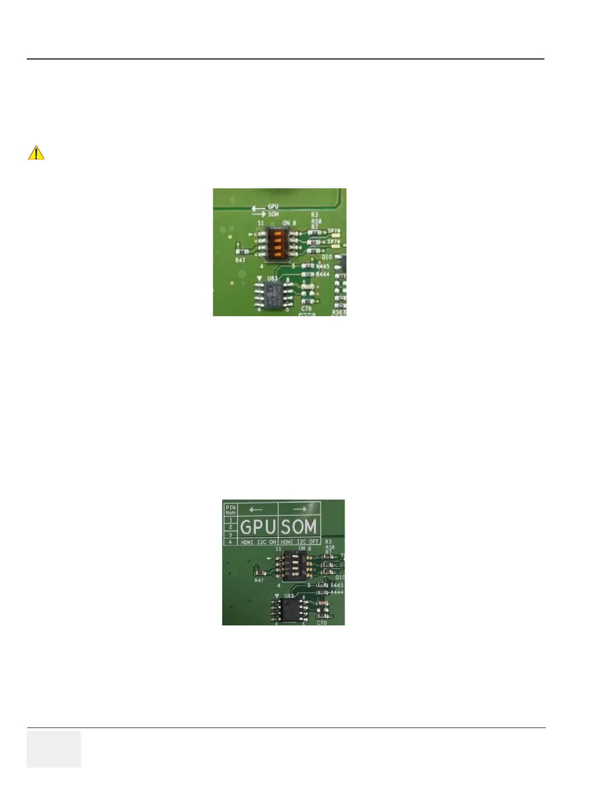
NOTE: Check S1. if GPU is mounted, PIN number 1,2,3 of the switch should be located in left.
-If GPU is not mounted, PIN number 1,2,3 of the swtich should be located in right.
-If UVC option is included, PIN number 4 of the switch should be located in left.
-If UVC option is not included, PIN number 4 of the swtich should be located in right.
C
Check S1. If GPU is mounted, 4 pin of the switch should be located in the left side. If GPU is not
moutned, 4 pin of the switch should be located in the right side.
Figure 8-191 Location of 4 pin of switch
Figure 8-192 Location of 4 pin of switch
 Loading...


