GE RAFT VOLUSON™ P8 / VOLUSON™ P6
DIRECTION 5723243, R
EVISION 6 DRAFT (MAY 23, 2018) BASIC SERVICE MANUAL
8-72 Section 8-23 - Replacement of LCD Cable
Section 8-23
Replacement of LCD Cable
8-23-1 Manpower
One person, 15 minutes
8-23-2 Tools
Philips screw driver, Flat-blade screwdriver, wrench, Pincette, Cutter
8-23-3 Disassembly Procedure
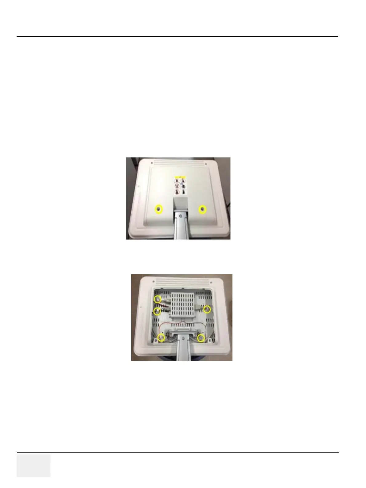
1.) Unscrew 2 screws to remove the MONITOR REAR CABINET BEZEL ASSY BT16. Refer to the
figure below.
2.) Unscrew 5 screws to disconnect the LCD Cables.
Figure 8-101 Unscrewing 2 screws to remove the MONITOR REAR CABINET BEZEL ASSY BT16
Figure 8-102 Unscrewing 5 screws to disconnect the LCD Cables
 Loading...


