EasyManuals Logo

GE Voluson P6 BT16 User Manual

GE Voluson P6 BT16
612 pages
To Next Page IconTo Next Page
To Previous Page IconTo Previous Page
Page #419 background imageLoading...
Page #419 background image
GE DRAFT VOLUSON™ P8 / VOLUSON™ P6
DIRECTION 5723243, R
EVISION 6 DRAFT (MAY 23, 2018) BASIC SERVICE MANUAL
Chapter 8 - Replacement Procedures 8-71
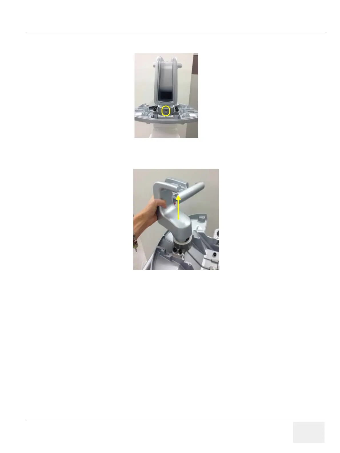
7.) Unscrew LCD ARM STOPPER SCREW. Refer to figure below.
8.) Pull out the LCD ARM from the LCD ARM HOLDER
8-22-4 Installation Procedure
1.) Install the new parts in the reverse order of removal.
2.) Perform: FRU8-9: Replacement of the MONITOR STAND ARM - Functional Tests.
Figure 8-99 Unscrewing LCD ARM STOPPER SCREW
Figure 8-100 Pulling out the LCD ARM from the LCD ARM HOLDER

Table of Contents

Questions and Answers:

Question and Answer IconNeed help?

Do you have a question about the GE Voluson P6 BT16 and is the answer not in the manual?

GE Voluson P6 BT16 Specifications

General IconGeneral
BrandGE
ModelVoluson P6 BT16
CategoryMedical Equipment
LanguageEnglish

Related product manuals