GE RAFT VOLUSON™ P8 / VOLUSON™ P6
DIRECTION 5723243, R
EVISION 6 DRAFT (MAY 23, 2018) BASIC SERVICE MANUAL
8-68 Section 8-21 - Replacement of Monitor
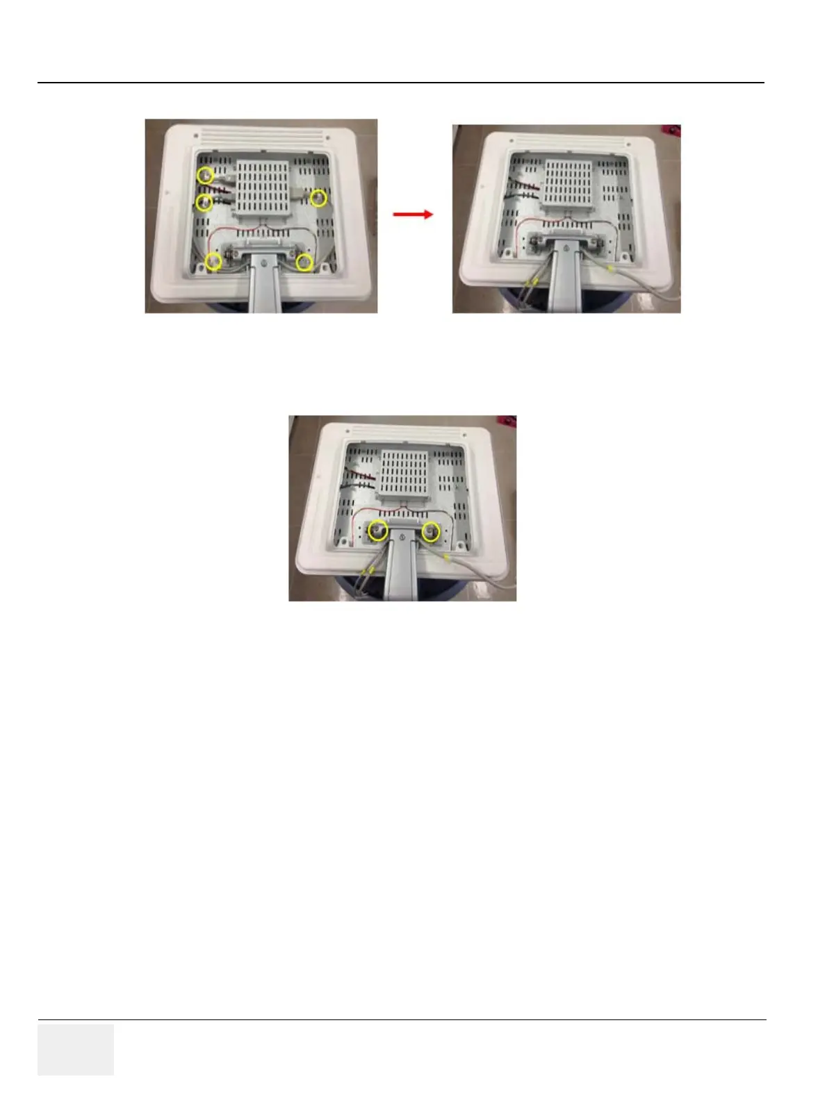
2.) Unscrew 5 screws to disconnect the LCD cables.
3.) One person grab the MONITOR. the other person should unscrew the 2 hexagonal socket screws
and then separate the MONITOR for the LCD ARM. Refer to the figure below.
8-21-4 Installation Procedure
1.) Install the new parts in the reverse order of removal.
2.) Perform: FRU8-8: Replacement of Monitor - Functional Tests.
Figure 8-92 Unscrewing 5 screws to disconnect the LCD cables
Figure 8-93 Unscrewing 2 hexagonal screws to separate MONITOR
 Loading...


