HYDRAULIC SYSTEM
B2050, B2350, B2650, B3150, WSM
8-M6
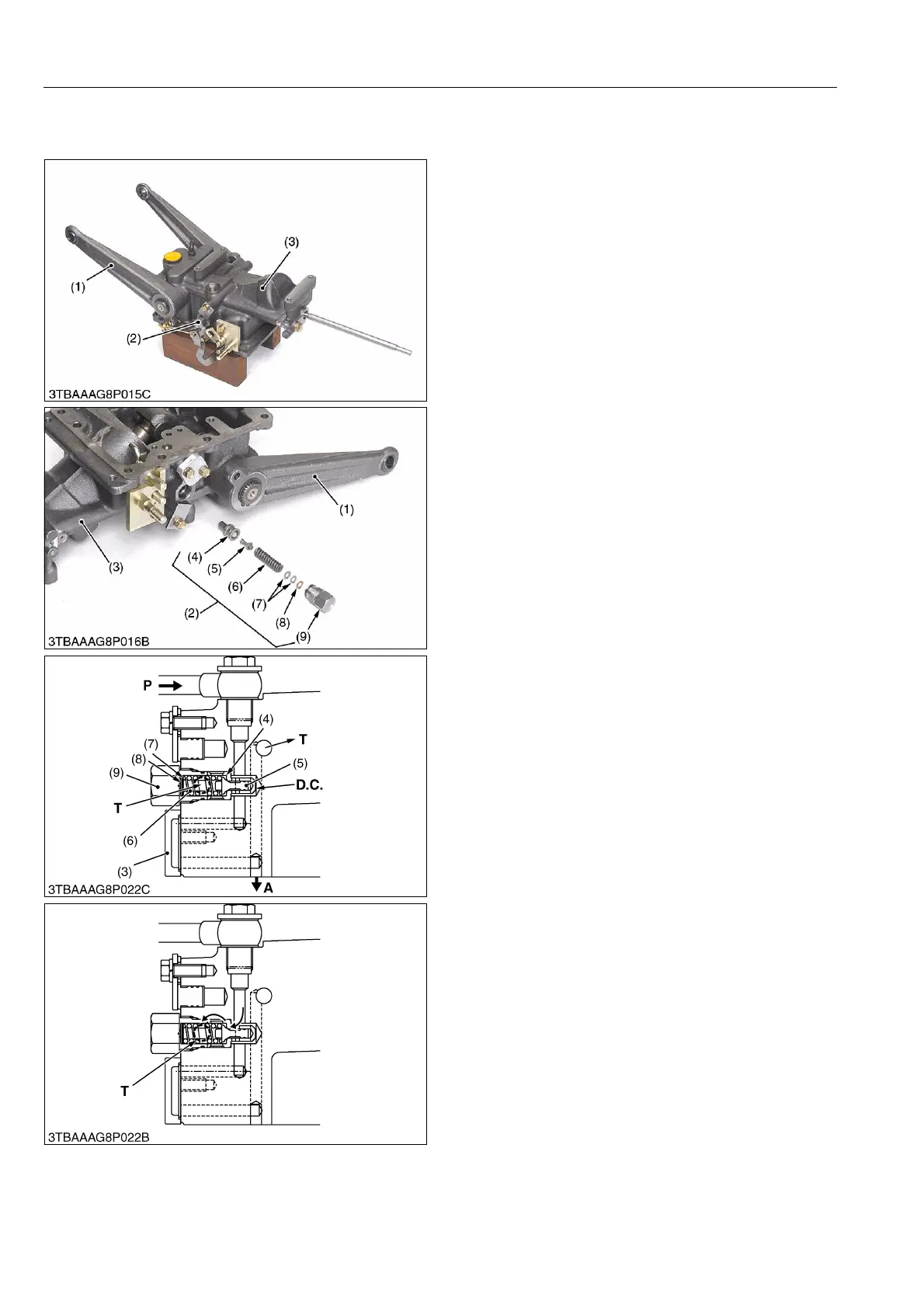
[2] RELIEF VALVE
(1) Manual Transmission Model (Without Front Loader Valve)
Relief valve is located at the hydraulic cylinder right
hand side.
The implement control system circuit has a relief
valve to restrict the maximum pressure in the circuit.
The relief valve is a guide piston type with damping
effect.
Among direct acting relief valves, this type is suited
to higher pressure and has larger capacity. Furthermore,
this type is free from unstable operation, such as
chattering, which occurs often in direct acting relief
valves.
As shown in the figure, the guide is attached to the
poppet (5) and a valve chamber D.C. (called the
damping chamber) is formed at the bottom of the poppet
(5). The inlet of the valve leads to the chamber via a
clearance between the sliding portion of the poppet (5)
and the valve seat (4), minimizing valve vibration with the
damping effect of the chamber.
As the oil pressure in the circuit increases, so does
the pressure in the damping chamber D.C.. When the
pressure rises above the valve setting and overcomes
the spring force, the valve opens. Oil then flows out to
the transmission case through T port, preventing any
further rise in pressure. The valve closes again when
enough oil is released to drop pressure below the valve
setting pressure.
(Reference)
• Relief valve setting pressure
15.5 to 16.5 MPa
158 to 168 kgf/cm
2
2248 to 2393 psi
Condition
• Engine speed
Approx. 2500 min
-1
(rpm)
• Oil temperature
50 °C (122 °F)
9Y1210982HYM0007US0
(1) Lift Arm
(2) Relief Valve
(3) Lift Cylinder
(4) Valve Seat
(5) Poppet
(6) Spring
(7) Shim
(8) Washer
(9) Plug
A: To Position Control Valve
P: Pump Port
(from Hydraulic Pump)
T: Tank Port
(to Transmission case)
D.C.:Damping Chamber
 Loading...

