ELECTRICAL SYSTEM
B2050, B2350, B2650, B3150, WSM
9-S15
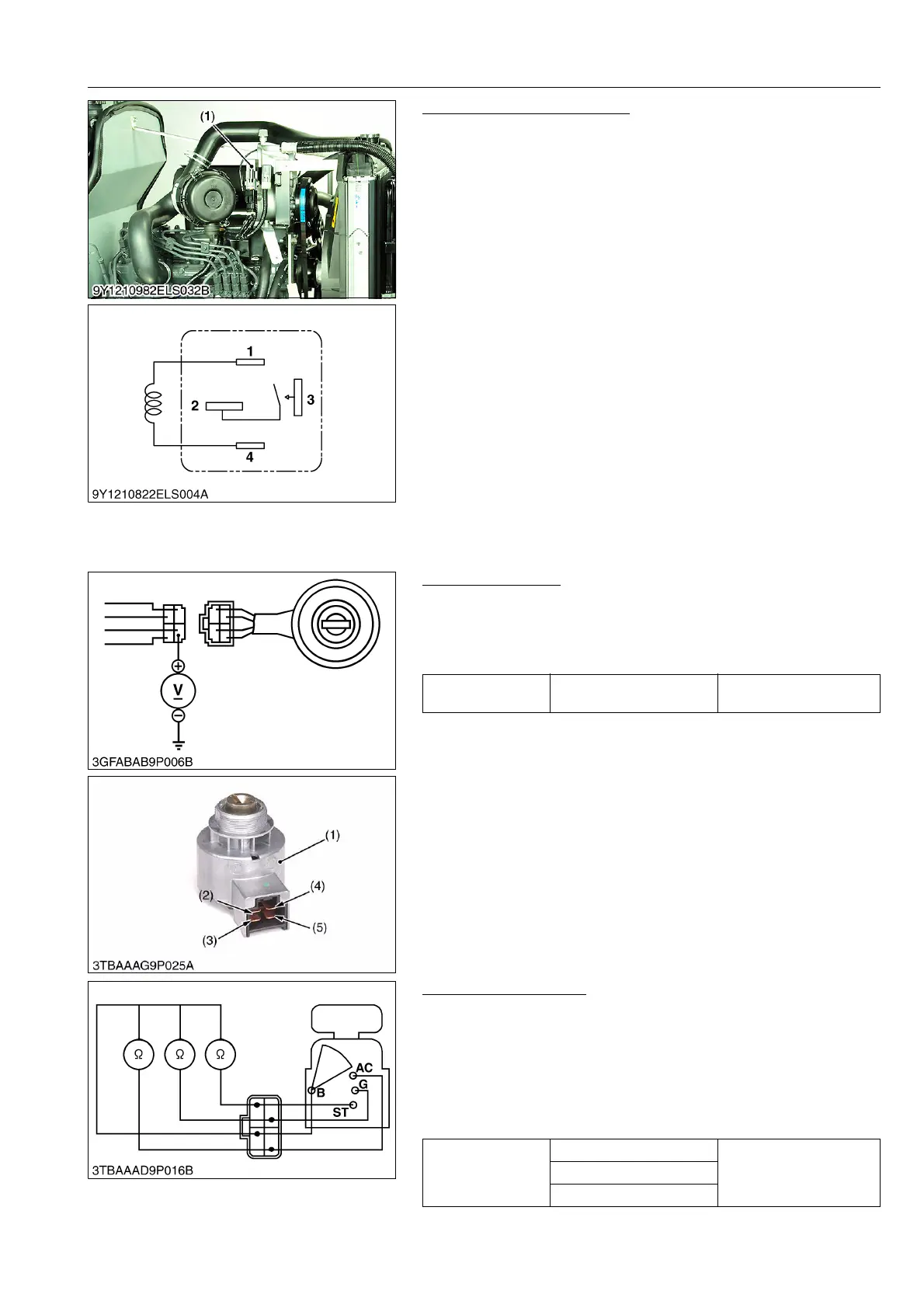
Relay (Glow) (CABIN Model)
1. Remove the relay.
2. Apply battery voltage across 2 terminal and 4 terminal, and
check for continuity across 1 terminal and 3 terminal.
3. If 0 is not indicated, renew the relay.
9Y1210982ELS0016US0
[4] STARTING SYSTEM
(1) Key Switch
Connector Voltage
1. Measure the voltage with a voltmeter across the connector B
terminal (2) and chassis.
2. If the voltage differs from the battery voltage (11 to 14 V), the
wiring harness is damaged.
9Y1210982ELS0017US0
Key Switch Continuity
1) Key Switch Key at "OFF" Position
1. Set the key switch OFF position.
2. Measure the resistance with an ohmmeter across the B terminal
and the AC terminal, B terminal and ST terminal, B terminal and
G terminal.
3. If infinity is not indicated, the contacts of the key switch are
damaged.
9Y1210982ELS0018US0
(1) Relay (Glow)
Voltage
Connector B terminal –
Chassis
Approx. battery voltage
(1) Main Switch
(2) B Terminal
(3) AC Terminal
(4) ST Terminal
(5) G Terminal
Resistance
B terminal – AC terminal
InfinityB terminal – ST terminal
B terminal – G terminal
 Loading...

