HYDRAULIC SYSTEM
B2050, B2350, B2650, B3150, WSM
8-S10
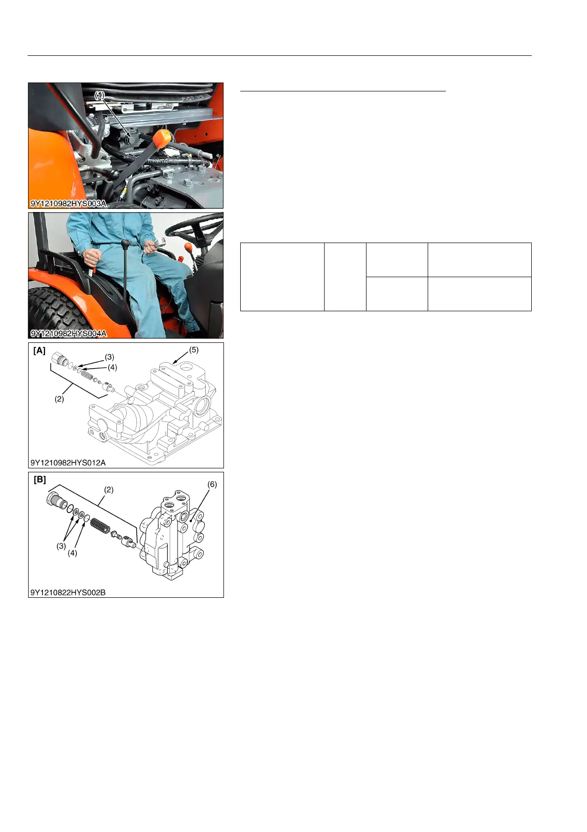
(3) 3-Points Hitch Relief Valve
3-Points Hitch Relief Valve Setting Pressure
1. Remove the seat under cover.
2. Remove the plug (1) from the hydraulic cylinder block (5).
3. Install the adaptor 58 (See page G-50.). Then connect the cable
and the pressure gauge to the adaptor.
4. Remove the feed back rod lock nut.
5. Start the engine and set the maximum speed.
6. Move the hydraulic control lever all way up to operate the relief
valve and measure the pressure.
7. If the pressure is not factory specifications, adjust the relief
valve setting pressure with the adjusting shims (4).
8. After checking the pressure, reinstall the feedback rod lock nut
and the plug (1).
Condition
• Engine rated speed
2500 min
-1
(rpm)
• Oil temperature
50 °C (122 °F)
(Reference)
[Manual Transmission Model (Without Front Loader Valve)]
• Thickness of shims (4)
0.1 mm (0.0039 in.)
0.2 mm (0.0079 in.)
0.4 mm (0.0160 in.)
[HST Model (With Front Loader Valve)]
• Thickness of shims (4)
0.10 mm (0.0039 in.)
0.20 mm (0.0079 in.)
0.40 mm (0.016 in.)
0.60 mm (0.024 in.)
9Y1210982HYS0008US0
Relief valve setting
pressure
Factory
specifi-
cation
Manual
transmission
model
15.5 to 16.5 MPa
158 to 168 kgf/cm
2
2248 to 2393 psi
HST Model
16.5 to 16.9 MPa
169 to 172 kgf/cm
2
2400 to 2450 psi
(1) Plug
(2) Relief Valve
(3) Plain Washer
(4) Shim
(5) Hydraulic Cylinder Block
(6) Front Loader Valve
[A] Manual Transmission Model
(Without Front Loader Valve)
[B] HST Model (With Front Loader
Valve)
 Loading...

