ELECTRICAL SYSTEM
B2050, B2350, B2650, B3150, WSM
9-S26
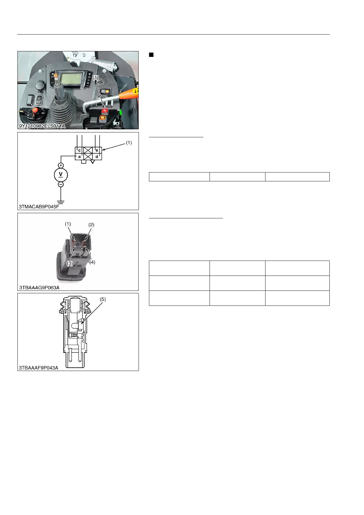
(3) Hazard Switch (Cabin Model Only)
• Refer to the page 9-M25 for the hazard switch (CABIN
model).
9Y1210982ELS0050US0
Connector Voltage
1. Connect the battery negative code, then measure the voltage
with a voltmeter across the a terminal and chassis.
2. If the voltage differ from the battery voltage, the wiring harness
is damaged.
9Y1210982ELS0051US0
Hazard Switch Continuity
1. Measure the resistance with ohmmeter across the a terminal (1)
and c terminal (3), and across the d terminal (2) and e terminal
(4).
2. If the measurement is not following below, the hazard switch or
the bulb are damaged.
9Y1210982ELS0052US0
(1) Hazard Switch
Voltage a terminal – Chassis Approx. battery voltage
(1) 4P Connector (for Hazard Switch)
Resistance
(Switch at OFF)
a terminal – c terminal Infinity
Resistance
(Switch at ON)
a terminal – c terminal 0
Resistance
(Bulb)
d terminal – e terminal Approx. 13
(1) a Terminal
(2) d Terminal
(3) c Terminal
(4) e Terminal
(5) Bulb
 Loading...

