ELECTRICAL SYSTEM
B2050, B2350, B2650, B3150, WSM
9-S37
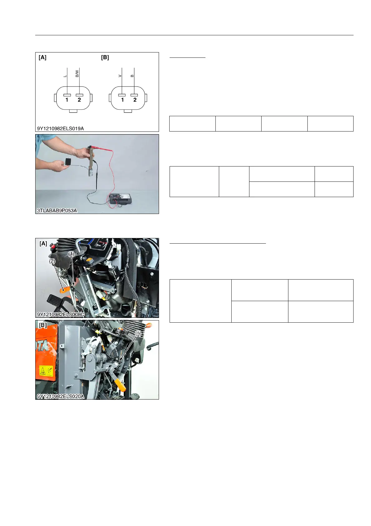
(6) Fuel Sensor
Fuel Sensor
1) Connector Voltage
1. Disconnect the connector and turn the key switch "ON"
position.
2. Measure the voltage with a voltmeter across the terminals
shown in the table below.
3. If the reference value is not indicated as shown in the table
below, check the relating electric circuit.
2) Sensor Continuity
1. Remove the fuel lever sensor from the fuel tank.
2. Measure the resistance across the sensor terminal and its body.
3. If the reference value are not indicated, the sensor is damaged.
9Y1210982ELS0070US0
(7) Bi-speed Turn Switch
Bi-speed Turn Switch Continuity
1. Disconnect the switch connector.
2. Connect the circuit tester to the switch connector.
3. Measure the resistance between terminals.
4. If the switch is damaged, replace it.
9Y1210982ELS0071US0
Voltage
Key switch at
"ON"
Terminal 1 –
chassis
Approx. 5 V
Resistance
(Sensor terminal –
its body)
Reference
value
Float at upper-most
position
2 to 4
Float at lower-most
position
109 to 111
(1) Fuel Sensor Connector (Harness
Side)
[A] ROPS Model
[B] CABIN Model
Bi-speed turn switch
When bi-speed turn
lever is at normal 4WD
position
Infinity
When bi-speed turn
lever is at bi-speed
turn 4WD position
0
(1) Bi-speed Turn Switch [A] ROPS Model
[B] CABIN Model
 Loading...

