HYDRAULIC SYSTEM
B2050, B2350, B2650, B3150, WSM
8-S22
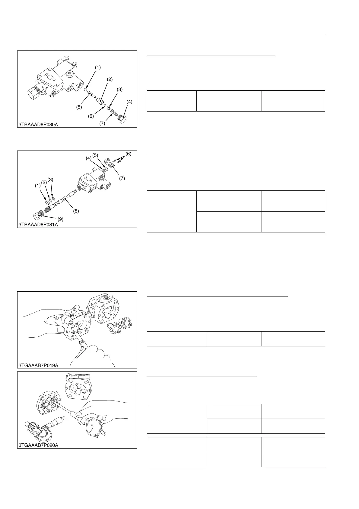
(7) Remote Control Valve (If Equipped)
Poppet and Piston (Mechanical Check Valve)
1. Remove the plug 1 (4) and draw out the spring (7), ball guide
(3), balls (1), (6), poppet (2) and piston (5).
(When reassembling)
• Take care not to damage the O-ring.
9Y1210982HYS0030US0
Spool
1. Remove the screws (6), and remove the bracket (7).
2. Remove the plug 2 (9), and draw out the spool (8).
(When reassembling)
• Take care not to damage the O-rings and backup rings.
9Y1210982HYS0031US0
[3] SERVICING
Clearance between Tip of Gear Tooth and Casing
1. Measure the clearance between gear and casing at several
points with feeler gauge.
2. If the clearance exceeds the allowable limit, replace the
assembly.
9Y1210982HYS0032US0
Clearance between Bushing and Shaft
1. Measure the shaft O.D. with an outside micrometer.
2. Measure the bushing I.D. with a cylinder gauge.
3. If the clearance exceeds the allowable limit, replace it.
9Y1210982HYS0033US0
Tightening torque Plug 1
29.4 to 49.0 N·m
3.0 to 5.0 kgf·m
21.7 to 36.2 lbf·ft
(1) Ball
(2) Poppet
(3) Ball Guide
(4) Plug 1
(5) Piston
(6) Ball
(7) Spring
Tightening torque
Bracket mounting screw
4.9 to 7.8 N·m
0.5 to 0.8 kgf·m
3.6 to 5.8 lbf·ft
Plug 2
39.3 to 58.8 N·m
4.0 to 6.0 kgf·m
28.9 to 43.4 lbf·ft
(1) Collar
(2) Backup Ring
(3) O-ring
(4) O-ring
(5) Backup Ring
(6) Screw
(7) Bracket
(8) Spool
(9) Plug 2
Clearance between tip of
gear tooth and casing
Allowable limit
0.15 mm
0.0059 in.
Clearance between
bushing and shaft
Factory specification
0.020 to 0.091 mm
0.0008 to 0.0036 in.
Allowable limit
0.12 mm
0.0047 in.
Shaft O.D. Factory specification
14.970 to 14.980 mm
0.5894 to 0.5898 in.
Bushing I.D. Factory specification
15.000 to 15.061 mm
0.5906 to 0.5930 in.
 Loading...

