ELECTRICAL SYSTEM
B2050, B2350, B2650, B3150, WSM
9-S32
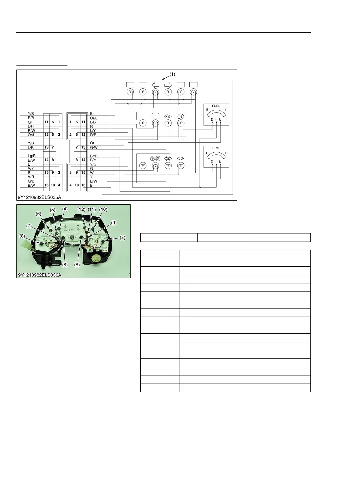
[7] WARNING LAMP, INDICATOR LAMP AND GAUGE
(1) Instrument Panel (ROPS Model)
Connector Voltage
1. Turn on the key switch.
2. Measure the voltage between terminal 2 and chassis.
3. If the measurement is not approximately battery voltage, check
the relating circuit.
[Connector Pin Arrangement]
9Y1210982ELS0063US0
(1) Instrument Panel
(2) Connector (Panel)
(3) Connector (Wire Harness)
(4) Oil Switch Lamp
(5) Charge Lamp
(6) Turn Signal Lamp (R)
(7) Glow Lamp
(8) Illumination Lamp
(9) Bi-speed Turn Indicator Lamp
(10) Turn Signal Lamp (L)
(11) Trailer Indicator Lamp
(12) Position Lamp
Voltage Terminal 2 – Chassis Approx. battery voltage
Terminal No. Item
1 Illumination
2 Key Switch
3 Fuel Gauge
4 Coolant Temperature Sensor
5 Turn Signal (R)
6 Turn Signal (L)
7 Position
8 Trailer Socket (+)
9 Bi-speed Turn Indicator
10 Oil Switch ()
11 Charge (+)
12 Glow Indicator
13 Oil Switch
14 Trailer Indicator ()
15 Charge ()
16 GND
 Loading...

