HYDRAULIC SYSTEM
B2050, B2350, B2650, B3150, WSM
8-M22
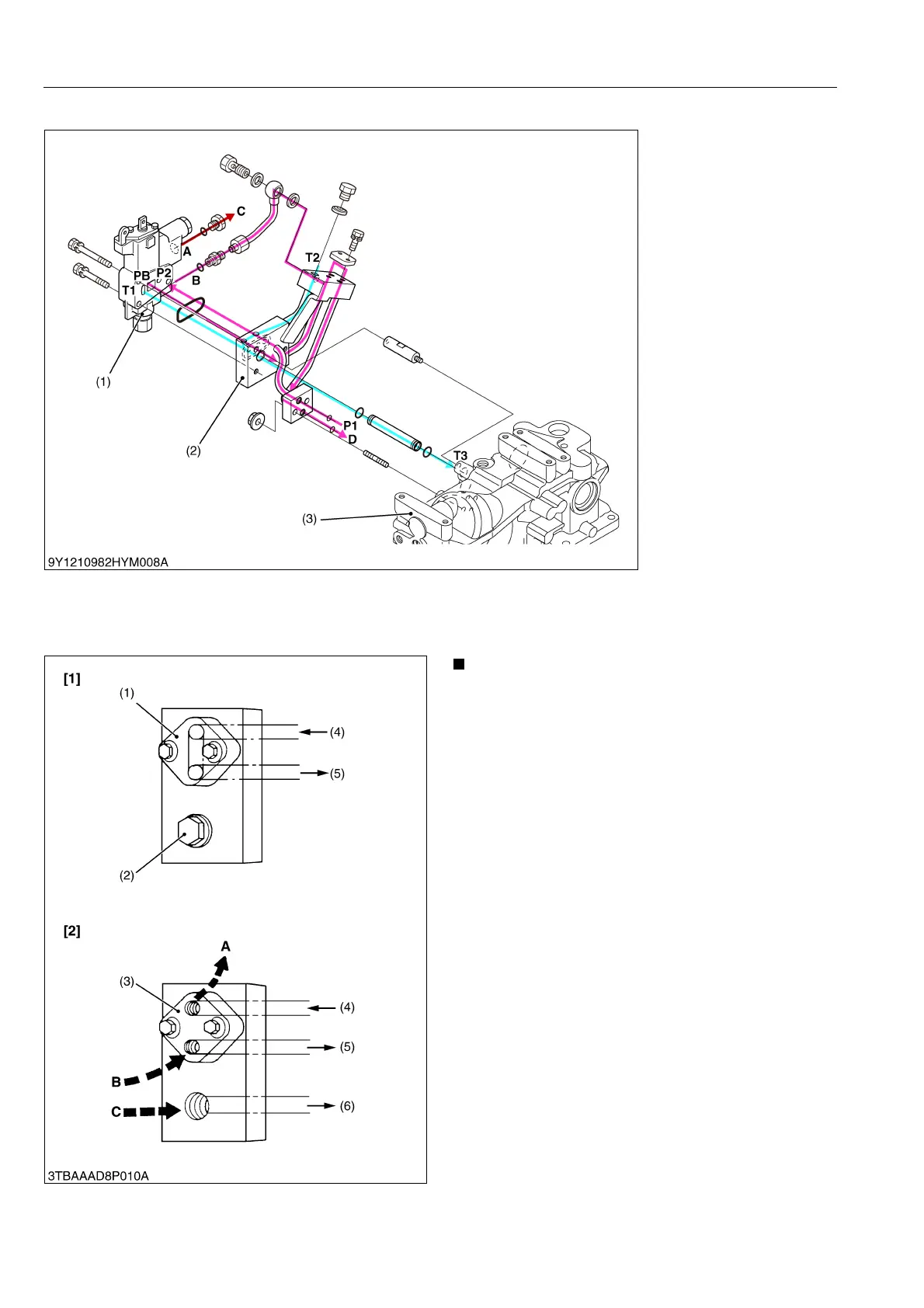
(2) Rear Hydraulic Outlet
The rear hydraulic outlet is located at the right hand side of the hydraulic cylinder body.
This rear hydraulic outlet is provided to take power out from the tractor to operate the hydraulic cylinders on the
implement.
9Y1210982HYM0027US0
• If the control valve of implement has the relief
valve, the tank port flow from implement should
be connected to the port C.
9Y1210982HYM0028US0
(1) Auxiliary Control Valve
(2) Rear Hydraulic Outlet
(3) Hydraulic Cylinder Body
A: From A Port of Remote
Control Valve
B: From B Port of Remote
Control Valve
C: To Implement
D: To Position Control Valve
P1: From Hydraulic Pump
P2: To P Port of Remote
Control Valve
PB: To PB Port of Remote
Control Valve
T1: From T Port of Remote
Control Valve
T2: From Implement (Drain)
T3: To Transmission Case
(1) Block Cover
(2) Plug
(3) Block Outlet Cover (Option)
(4) From Hydraulic Pump
(5) To Position Control Valve
(6) To Transmission Case
[1] When implement is not
attached
[2] When implement is
attached
A: To implement (Inlet) Max.
flow 17 L/min.
(4.5 U.S.gals/min.,
3.7 Imp.gals/min.)
Max. pressure
13.2 to 13.7 MPa
(135 to 140 kgf/cm
2
,
1920 to 1992 psi)
B: From Implement (Outlet)
C: From Implement (Drain)
 Loading...

