CABIN
B2050, B2350, B2650, B3150, WSM
10-S23
(2) Control Panel (Blower Switch, A/C Switch, Mode Control Dial and
Temperature Control Dial)
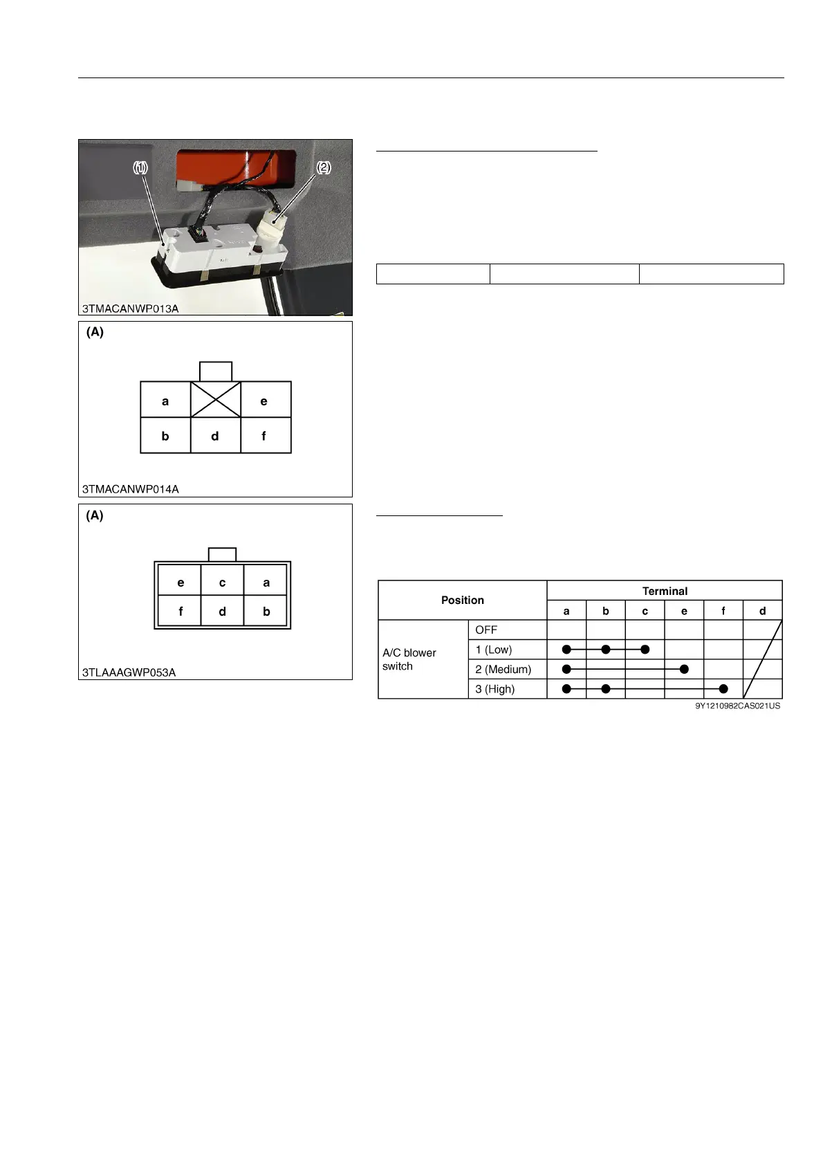
Blower Switch Connector Voltage
1. Disconnect the 6P connector (2) from blower switch.
2. Turn the main switch to "ON" position.
3. Measure the voltage with a voltmeter across the connector
terminal a and terminal b.
4. If the voltage differs from the battery voltage, the wiring harness,
A/C relay, fuse or main switch is damaged.
9Y1210982CAS0037US0
Blower Switch Test
1. Check the continuity through the switch with an ohmmeter.
2. If the continuity specified below are not indicated, the switch is
damaged.
9Y1210982CAS0038US0
Voltage Terminal a – Terminal b Approx. battery voltage
(1) Control Panel
(2) 6P Connector
(A) 6P Connector (Wire Harness
Side)
(A) 6P Connector
(Blower Switch Side)
 Loading...

