HYDRAULIC SYSTEM
B2050, B2350, B2650, B3150, WSM
8-S15
Separating Hydraulic Cylinder from Tractor Body
1. Disconnect the hydraulic delivery pipe from hydraulic cylinder.
2. Remove the hydraulic cylinder.
9Y1210982HYS0020US0
(5) 3-Points Hitch: Hydraulic Cylinder
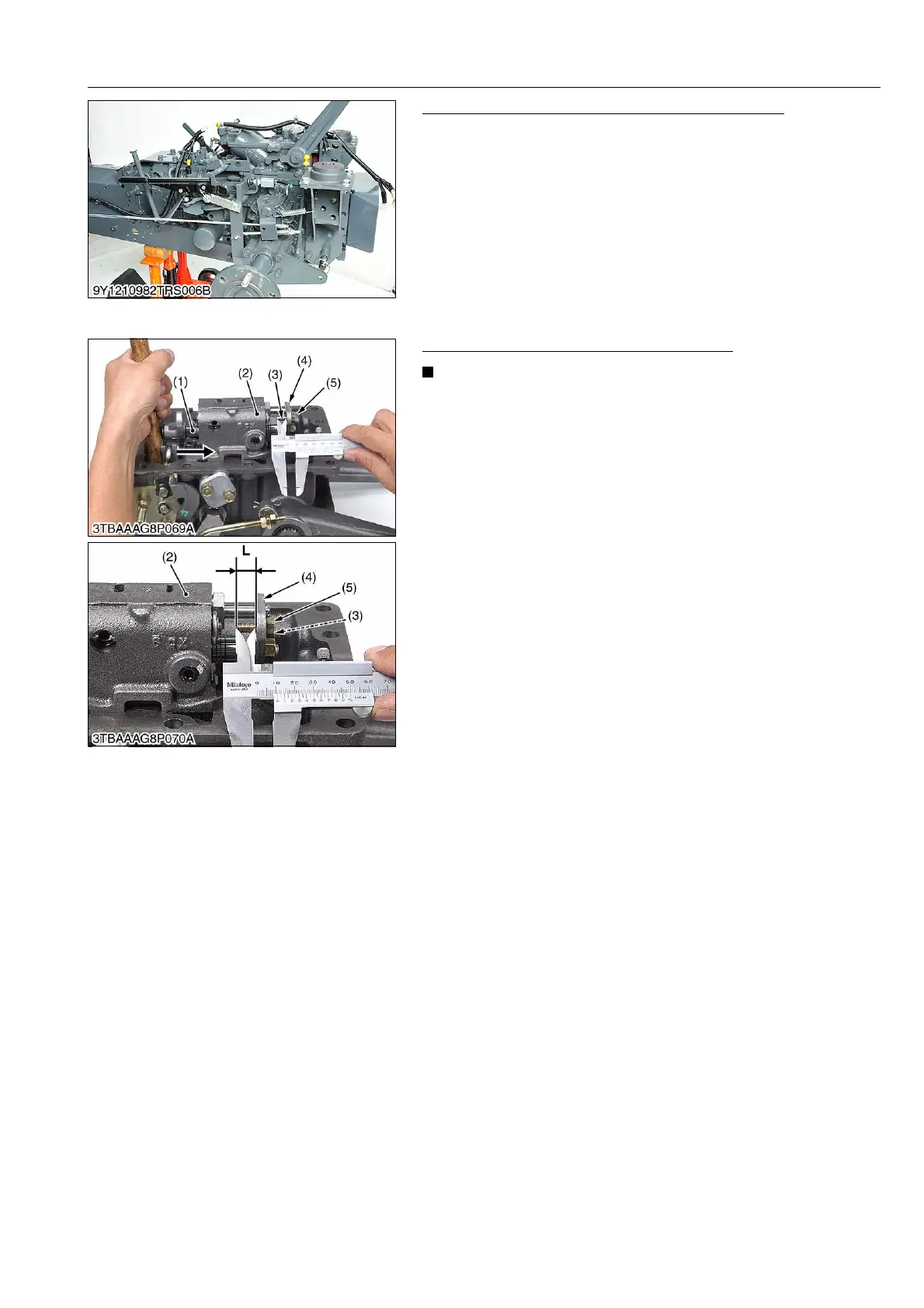
Checking the Length of the Adjusting Bolt
• Before disassembling the control valve, check the length of
the adjusting bolt.
1. Push the spool (1) into the control valve (2).
2. Check the length "L" of the adjusting bolt (3) as shown in the
picture.
(Reference)
• Length L
Approx. 10.70 mm (0.421 in.)
9Y1210982HYS0021US0
(1) Spool
(2) Control Valve
(3) Adjusting Bolt
(4) Connecting Plate
(5) Nut
L: Length of the adjusting bolt
 Loading...

