ELECTRICAL SYSTEM
B2050, B2350, B2650, B3150, WSM
9-S34
Connector Voltage
1. Disconnect the connector of connector 2 side.
2. Measure the voltage between terminal 15 (+) (Yellow/Blue) and
terminal 11 () (Black).
3. Turn the main key switch ON.
4. Measure the voltage between terminal 16 (+) (Brown) and
terminal 11 () (Black).
5. If the measure is not approximately battery voltage, check the
relating electric circuit.
9Y1210982ELS0065US0
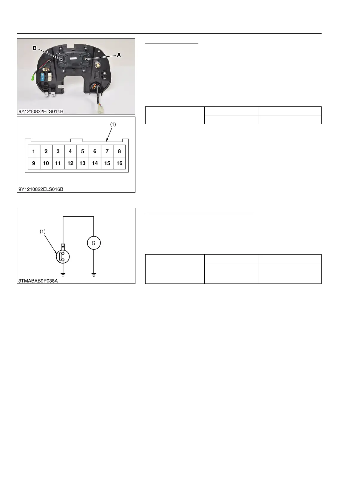
(3) Engine Oil Pressure Switch
Engine Oil Pressure Switch Continuity
1. Measure the resistance with an ohmmeter across the switch
terminal and the chassis.
2. If 0 is not indicated in the normal state, the switch is damaged.
3. If infinity is not indicated at pressure over 49 kPa (0.50 kgf/cm
2
,
7.1 psi), the switch is damaged.
9Y1210982ELS0066US0
Voltage
Ter mi na l 15 – 11 Approx. battery voltage
Ter mi na l 16 – 11 Approx. battery voltage
(1) Connector (Harness Side) A: Connector 1
B: Connector 2
Resistance (Switch
terminal – Chassis)
In normal state 0
At pressure over
approx. 49 kPa
(0.50 kgf/cm
2
, 7.1 psi)
Infinity
(1) Engine Oil Pressure Switch
 Loading...

