R01UH0823EJ0100 Rev.1.00 Page 548 of 1823
Jul 31, 2019
RX23W Group 23. Multi-Function Timer Pulse Unit 2 (MTU2a)
(2) Example of Reset-Synchronized PWM Mode Operation
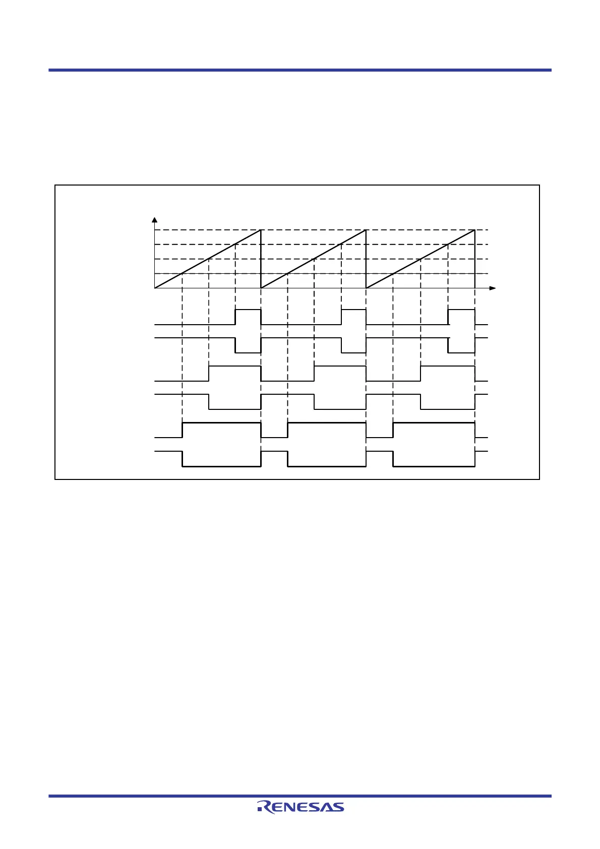
Figure 23.36 shows an example of operation in the reset-synchronized PWM mode.
Counters MTU3.TCNT and MTU4.TCNT operate as up-counters. The counters are cleared when a compare match
occurs between the MTU3.TCNT counter and the MTU3.TGRA register, and then begin incrementing from 0000h. The
output from the PWM pins toggles every time a compare match occurs in registers MTU3.TGRB, MTU4.TGRA, and
MTU4.TGRB and the counters are cleared.
Figure 23.36 Example of Reset-Synchronized PWM Mode Operation (When TOCR1.OLSN = 1 and OLSP = 1)
0000h
MTIOC3B
MTIOC3D
MTIOC4A
MTIOC4C
MTIOC4B
MTIOC4D
Time
MTU3.TCNT and MTU4.TCNT
values
MTU3.TGRA
MTU3.TGRB
MTU4.TGRB
MTU4.TGRA

 Loading...


