Electrical connections:
All wiring must be in accordance with
Article 760 of NEC or the local building
codes.
A 2-conductor wire cable (P/N 600-
192239) is supplied with the ACM-1
module to use on the OMM-2 which is
installed in the left-hand position. Use
this cable to connect 24 VDC from P3
on the MMB-1/-2 to TB1 on the
OMM-2 module. When using a PSR-1,
connect two individual 14 AWG wires
between the OMM-2 TB1 and PSR-1
TB3-1 and TB3-2.
The terminals on OMM-2 TB1 are
marked +24V and RET.
On MMB-1/-2 P3, 1 is positive and
2 is negative.
On PSR-1 TB3, 1 is positive and 2
is negative.
On MMB-2 TB1, 5 is positive and 4
is negative.
Assign plug-in cards to the card edge
connectors. Once the terminal block
related to each edge connector is
wired, place only the assigned plug-in
card in that edge connector.
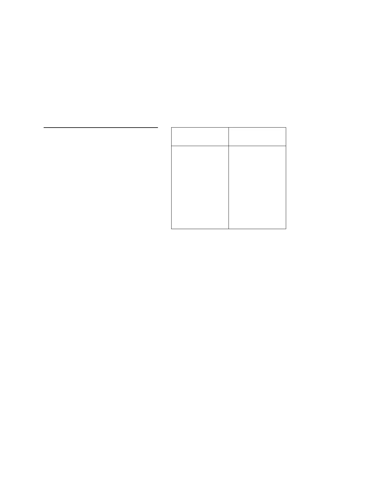
Refer to the Installation Instructions
listed in the following table for direc-
tions on wiring to the 22 position
OMM-2 terminal blocks and for attach-
ing these modules to the OMM-2
terminal blocks.
OMM-2 Connections and Ratings
4 - 63
If the system includes more than one
OMM-2, use the 14-conductor ribbon
cable (P/N 555-192155) to connect P1
of the first OMM-2 to P2 of the second
OMM-2. If there is a third OMM-2,
connect P1 of the second OMM-2 to
P2 of the third OMM-2. No more than
three OMM-2s can be connected
together in an MME-3 enclosure. In an
MLE-6 enclosure a maximum of six
OMM-2s can be installed provided the
OCC-1 submodule limit of 11 or the
power supply capacity as described in
Appendix D - MXL Power Supply
Load Calculations is not exceeded.
Note that there are two 8-conductor
cables. The long 8-conductor cable
(P/N 555-192243), comes with the
ACM-1. Use this cable for communica-
tions and power from P4 on the OMM-2
to either P6 on the PSR or to P6 on the
MMB-1/-2, whichever is present. This
Installation
Instructions Part Number
ASC-1
ASC-2
OCC-1
PLC-4
RCM-1
ZAC-30
ZC1-8B
ZC2-4AB
ZC2-8B
ZC3-4AB
ZCT-8B
315-091263
315-092085
315-090918
315-093312
315-093878
315-092960
315-090910
315-091262
315-092116
315-092089
315-092105
Technical Manuals Online! - http://www.tech-man.com

 Loading...


